How to Use Driver A4988 for Stepper: Examples, Pinouts, and Specs
Introduction
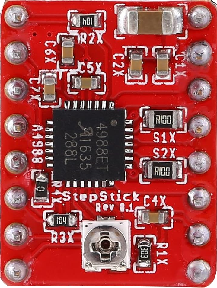
The A4988 is a microstepping driver designed for controlling bipolar stepper motors. It enables precise control of motor position and speed, making it ideal for applications requiring high accuracy and smooth motion. The driver supports microstepping resolutions of full-step, half-step, quarter-step, eighth-step, and sixteenth-step, allowing for fine-tuned motor control. Additionally, the A4988 features adjustable current control, over-temperature protection, and short-circuit protection, ensuring reliable operation in various environments.
Explore Projects Built with Driver A4988 for Stepper


Explore Projects Built with Driver A4988 for Stepper
Common Applications
- 3D printers
- CNC machines
- Robotics
- Automated camera sliders
- Precision positioning systems
Technical Specifications
Key Technical Details
- Operating Voltage (VMOT): 8V to 35V
- Logic Voltage (VDD): 3.3V to 5V
- Maximum Output Current: 2A per coil (with sufficient cooling)
- Microstepping Modes: Full, 1/2, 1/4, 1/8, 1/16 steps
- Current Control: Adjustable via onboard potentiometer
- Protection Features: Over-temperature, under-voltage lockout, and short-circuit protection
- Step Frequency: Up to 500 kHz
Pin Configuration and Descriptions
The A4988 driver module has 16 pins. Below is the pinout and description:
| Pin Name | Type | Description |
|---|---|---|
| VMOT | Power Input | Motor power supply (8V to 35V). Connect to the stepper motor power source. |
| GND | Power Ground | Ground connection for motor power supply. |
| VDD | Power Input | Logic power supply (3.3V to 5V). |
| GND | Power Ground | Ground connection for logic power supply. |
| 1A, 1B | Motor Output | Connect to one coil of the stepper motor. |
| 2A, 2B | Motor Output | Connect to the other coil of the stepper motor. |
| STEP | Logic Input | Pulse signal to control motor steps. |
| DIR | Logic Input | Direction control signal. |
| ENABLE | Logic Input | Enables or disables the driver (active low). |
| MS1, MS2, MS3 | Logic Input | Microstepping resolution selection pins. |
| RESET | Logic Input | Resets the driver (active low). |
| SLEEP | Logic Input | Puts the driver into low-power sleep mode (active low). |
| REF | Analog Input | Reference voltage for current control. Adjusted via the onboard potentiometer. |
Microstepping Resolution Table
The microstepping resolution is determined by the MS1, MS2, and MS3 pins:
| MS1 | MS2 | MS3 | Microstepping Mode |
|---|---|---|---|
| Low | Low | Low | Full Step |
| High | Low | Low | Half Step |
| Low | High | Low | Quarter Step |
| High | High | Low | Eighth Step |
| High | High | High | Sixteenth Step |
Usage Instructions
How to Use the A4988 in a Circuit
Power Connections:
- Connect VMOT and GND to the motor power supply (8V to 35V).
- Connect VDD and GND to the logic power supply (3.3V or 5V).
Motor Connections:
- Connect the stepper motor coils to the 1A, 1B, 2A, and 2B pins. Ensure the correct pairing of motor wires.
Control Signals:
- Connect the STEP pin to a microcontroller GPIO pin to send step pulses.
- Connect the DIR pin to a GPIO pin to control the motor's direction.
- Optionally, connect ENABLE, RESET, and SLEEP pins to GPIO pins or tie them to appropriate logic levels.
Microstepping Configuration:
- Set the MS1, MS2, and MS3 pins to the desired logic levels for the required microstepping mode.
Current Adjustment:
- Use the onboard potentiometer to set the reference voltage (VREF) for current control. The formula for current limit is: [ I_{max} = \frac{V_{REF}}{8 \times R_{sense}} ] where ( R_{sense} ) is typically 0.1Ω on most A4988 modules.
Cooling:
- If operating at high currents, attach a heatsink to the A4988 or ensure proper airflow to prevent overheating.
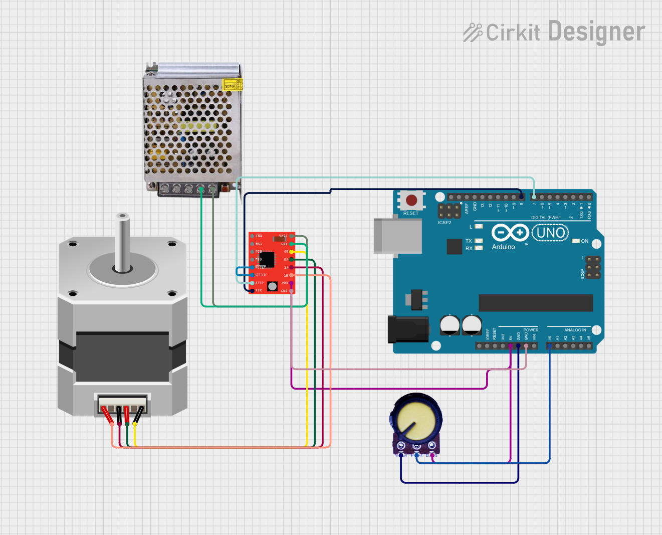
Example: Connecting to an Arduino UNO
Below is an example of how to control a stepper motor using the A4988 and an Arduino UNO:
// Define pin connections
#define STEP_PIN 3  // Connect to STEP pin on A4988
#define DIR_PIN 4   // Connect to DIR pin on A4988

void setup() {
  pinMode(STEP_PIN, OUTPUT); // Set STEP pin as output
  pinMode(DIR_PIN, OUTPUT);  // Set DIR pin as output

  digitalWrite(DIR_PIN, HIGH); // Set initial direction (HIGH or LOW)
}

void loop() {
  // Generate step pulses
  digitalWrite(STEP_PIN, HIGH); // Step pulse HIGH
  delayMicroseconds(500);       // Wait 500 microseconds
  digitalWrite(STEP_PIN, LOW);  // Step pulse LOW
  delayMicroseconds(500);       // Wait 500 microseconds
}
Important Considerations
- Always power the logic (VDD) before the motor power (VMOT) to avoid damaging the driver.
- Never disconnect the motor while the driver is powered, as this can cause voltage spikes that may damage the A4988.
- Use decoupling capacitors (e.g., 100 µF and 0.1 µF) across VMOT and GND to reduce noise and protect the driver.
Troubleshooting and FAQs
Common Issues and Solutions
Motor Not Moving:
- Verify all connections, especially the motor coil wiring.
- Ensure the STEP pin is receiving pulses from the microcontroller.
- Check the power supply voltage for VMOT and VDD.
Motor Vibrates but Does Not Rotate:
- Check the DIR pin logic level to ensure the correct direction.
- Verify the microstepping configuration (MS1, MS2, MS3).
Driver Overheating:
- Reduce the current limit using the potentiometer.
- Attach a heatsink or improve cooling.
Motor Skipping Steps:
- Increase the step pulse frequency gradually to avoid exceeding the motor's speed capability.
- Ensure the power supply can provide sufficient current.
FAQs
Q: Can I use the A4988 with a unipolar stepper motor?
A: No, the A4988 is designed for bipolar stepper motors only.
Q: How do I calculate the reference voltage (VREF) for my motor?
A: Use the formula ( V_{REF} = I_{max} \times 8 \times R_{sense} ). For example, if ( I_{max} = 1A ) and ( R_{sense} = 0.1Ω ), then ( V_{REF} = 0.8V ).
Q: What happens if I exceed the maximum current rating?
A: The A4988's over-temperature protection will activate, but prolonged overcurrent can damage the driver. Always set the current limit appropriately.
Q: Can I control multiple stepper motors with one Arduino?
A: Yes, you can control multiple A4988 drivers with separate STEP and DIR pins for each motor. Ensure the Arduino has enough GPIO pins and processing power for your application.