How to Use DC Circuit breaker: Examples, Pinouts, and Specs
Introduction
A DC circuit breaker is a protective device designed to automatically interrupt the flow of direct current (DC) in an electrical circuit. Its primary purpose is to prevent damage to electrical systems caused by overloads, short circuits, or other fault conditions. Unlike fuses, which need to be replaced after a fault, circuit breakers can be reset and reused, making them a reliable and cost-effective solution for circuit protection.
Explore Projects Built with DC Circuit breaker

Explore Projects Built with DC Circuit breaker
Common Applications and Use Cases
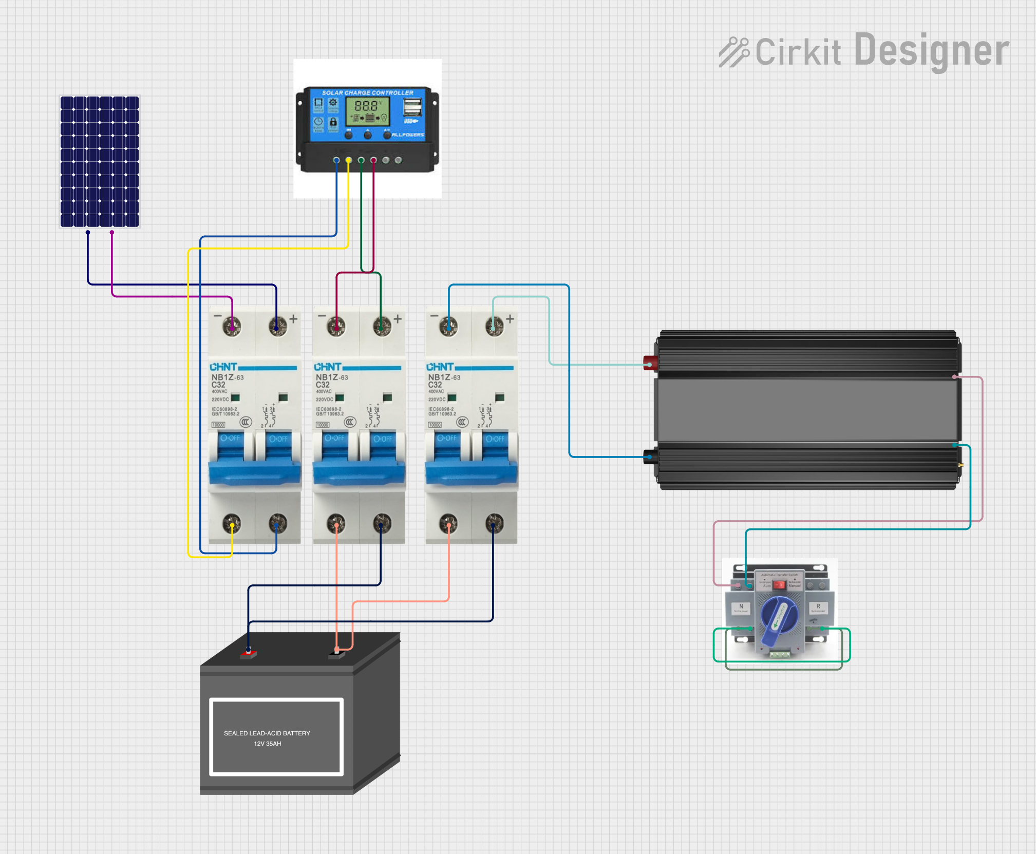
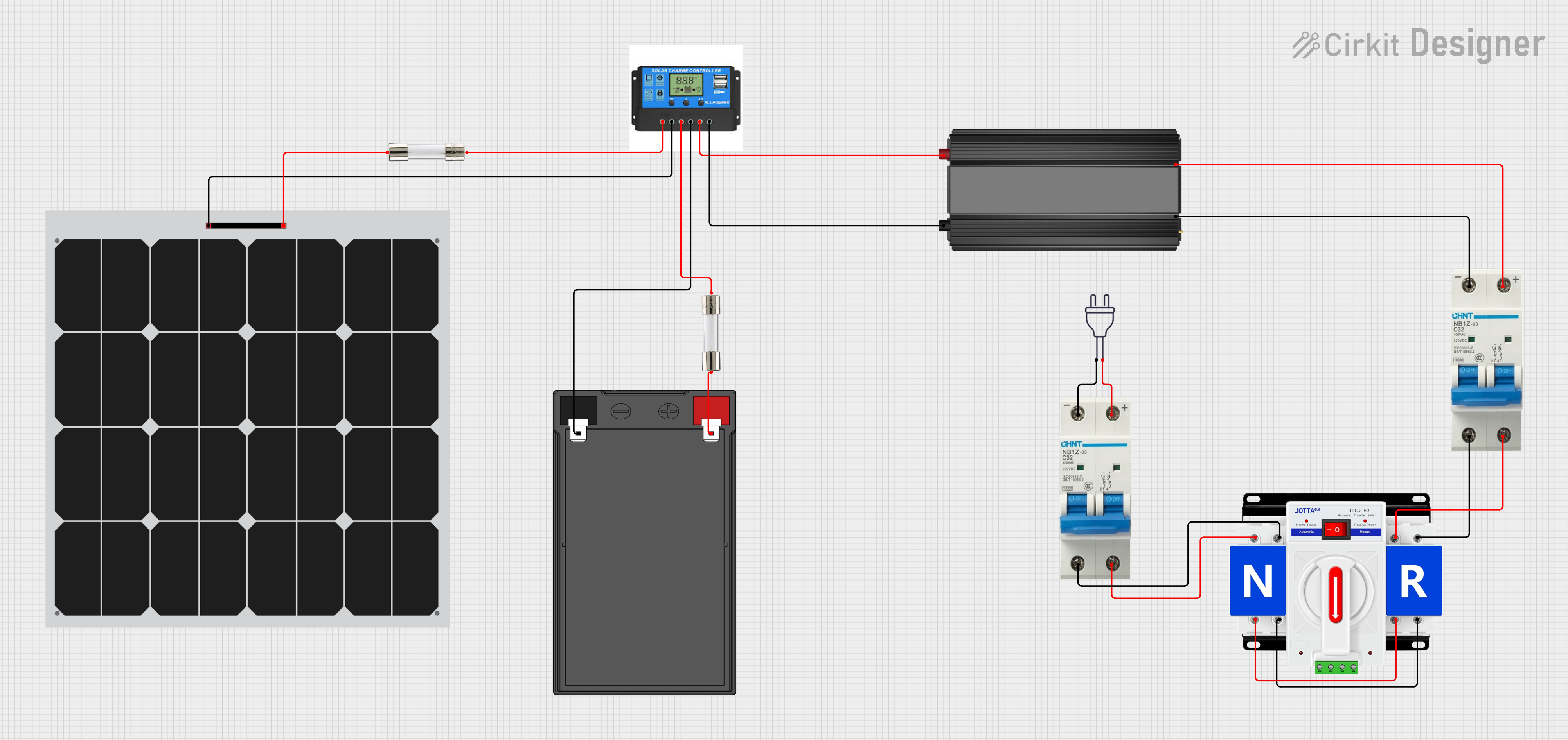
- Solar power systems to protect photovoltaic (PV) arrays and batteries.
- Electric vehicles (EVs) to safeguard high-voltage DC circuits.
- Industrial machinery and equipment powered by DC systems.
- Telecommunications systems to protect sensitive electronic components.
- Battery banks and energy storage systems.
Technical Specifications
Below are the key technical details for a typical DC circuit breaker. Specifications may vary depending on the model and manufacturer.
General Specifications
| Parameter | Value/Range |
|---|---|
| Rated Voltage | 12V DC to 1000V DC (varies by model) |
| Rated Current | 1A to 1000A (varies by model) |
| Breaking Capacity | 6kA to 50kA (varies by model) |
| Operating Temperature | -25°C to +70°C |
| Reset Type | Manual or Automatic |
| Mounting Style | DIN rail or panel-mounted |
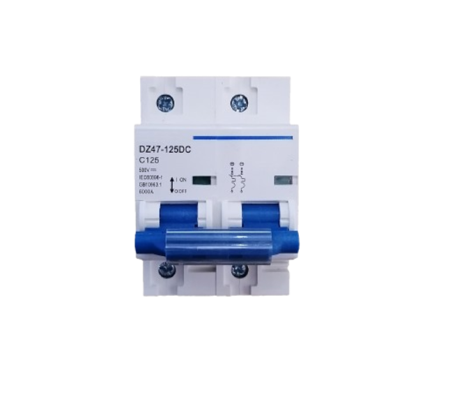
Pin Configuration and Descriptions
DC circuit breakers typically have two main terminals for connection. Below is a general description of the terminals:
| Terminal Name | Description |
|---|---|
| Line (Input) | Connects to the positive side of the DC power source. |
| Load (Output) | Connects to the load or downstream circuit. |
Some advanced DC circuit breakers may include auxiliary terminals for monitoring or remote control. Refer to the specific datasheet for details.
Usage Instructions
How to Use the Component in a Circuit
- Determine the Ratings: Select a DC circuit breaker with appropriate voltage and current ratings for your application. Ensure the breaking capacity exceeds the maximum fault current of your system.
- Connect the Terminals:
- Connect the Line (Input) terminal to the positive side of the DC power source.
- Connect the Load (Output) terminal to the load or downstream circuit.
- Secure the Breaker: Mount the circuit breaker on a DIN rail or panel, as per the manufacturer's instructions.
- Test the Circuit: After installation, test the circuit breaker by simulating an overload or short circuit to ensure proper operation.
Important Considerations and Best Practices
- Always ensure the circuit breaker is rated for DC applications. AC circuit breakers are not suitable for DC circuits due to differences in arc extinguishing mechanisms.
- Install the circuit breaker in a well-ventilated area to prevent overheating.
- Use appropriately sized wires and connectors to handle the rated current.
- For high-voltage DC systems, ensure proper insulation and spacing to avoid arcing.
- Regularly inspect the circuit breaker for signs of wear or damage.
Example: Using a DC Circuit Breaker with an Arduino UNO
While DC circuit breakers are not directly connected to microcontrollers like the Arduino UNO, they can be used in circuits powered by DC sources controlled by the Arduino. For example, you can use a DC circuit breaker to protect a motor driver circuit powered by a 12V DC source.
// Example code to control a motor driver circuit protected by a DC circuit breaker
// This code assumes the motor driver is connected to the Arduino UNO

const int motorPin = 9; // PWM pin connected to the motor driver

void setup() {
  pinMode(motorPin, OUTPUT); // Set motor pin as output
}

void loop() {
  analogWrite(motorPin, 128); // Run motor at 50% speed
  delay(5000); // Run for 5 seconds

  analogWrite(motorPin, 0); // Stop motor
  delay(2000); // Wait for 2 seconds
}

// Note: Ensure the DC circuit breaker is installed between the 12V DC source
// and the motor driver to protect the circuit from overloads or short circuits.
Troubleshooting and FAQs
Common Issues and Solutions
| Issue | Possible Cause | Solution |
|---|---|---|
| Circuit breaker trips frequently | Overload or short circuit in the circuit | Check the load and wiring for faults. |
| Circuit breaker does not trip | Fault current is below the breaker's rating | Use a breaker with a lower current rating. |
| Breaker overheats during operation | Poor ventilation or undersized breaker | Ensure proper ventilation and use a breaker with higher current capacity. |
| Cannot reset the breaker | Internal damage or persistent fault | Inspect the breaker and circuit for issues. Replace if necessary. |
FAQs
Can I use an AC circuit breaker in a DC circuit? No, AC circuit breakers are not designed for DC circuits and may fail to interrupt the current properly. Always use a breaker specifically rated for DC applications.
How do I choose the right DC circuit breaker? Consider the voltage, current, and breaking capacity requirements of your circuit. Ensure the breaker is rated for the maximum fault current and operating conditions.
What is the difference between a fuse and a circuit breaker? A fuse is a one-time-use device that must be replaced after a fault, while a circuit breaker can be reset and reused.
Can a DC circuit breaker protect against reverse polarity? No, a DC circuit breaker does not protect against reverse polarity. Use additional components like diodes or polarity protection circuits for this purpose.