
How to Use PICAXE-28X1: Examples, Pinouts, and Specs
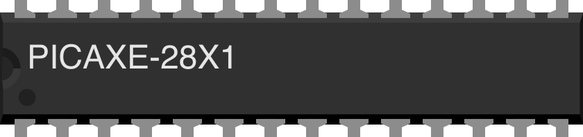
 Design with PICAXE-28X1 in Cirkit Designer
Introduction
The PICAXE-28X1 is a versatile microcontroller designed for educational and hobbyist projects. It features 28 pins, including both analog and digital I/O, and is programmable using a simple BASIC-like language. This makes it an excellent choice for beginners and those looking to quickly prototype electronic projects. The PICAXE-28X1 is widely used in robotics, home automation, data logging, and other applications requiring programmable control.
Explore Projects Built with PICAXE-28X1
 Open Project in Cirkit Designer
 Open Project in Cirkit Designer
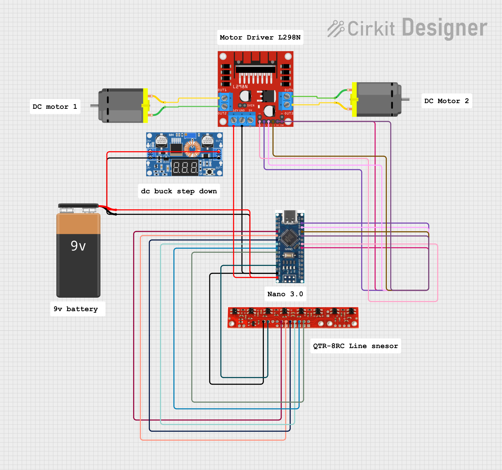 Open Project in Cirkit Designer
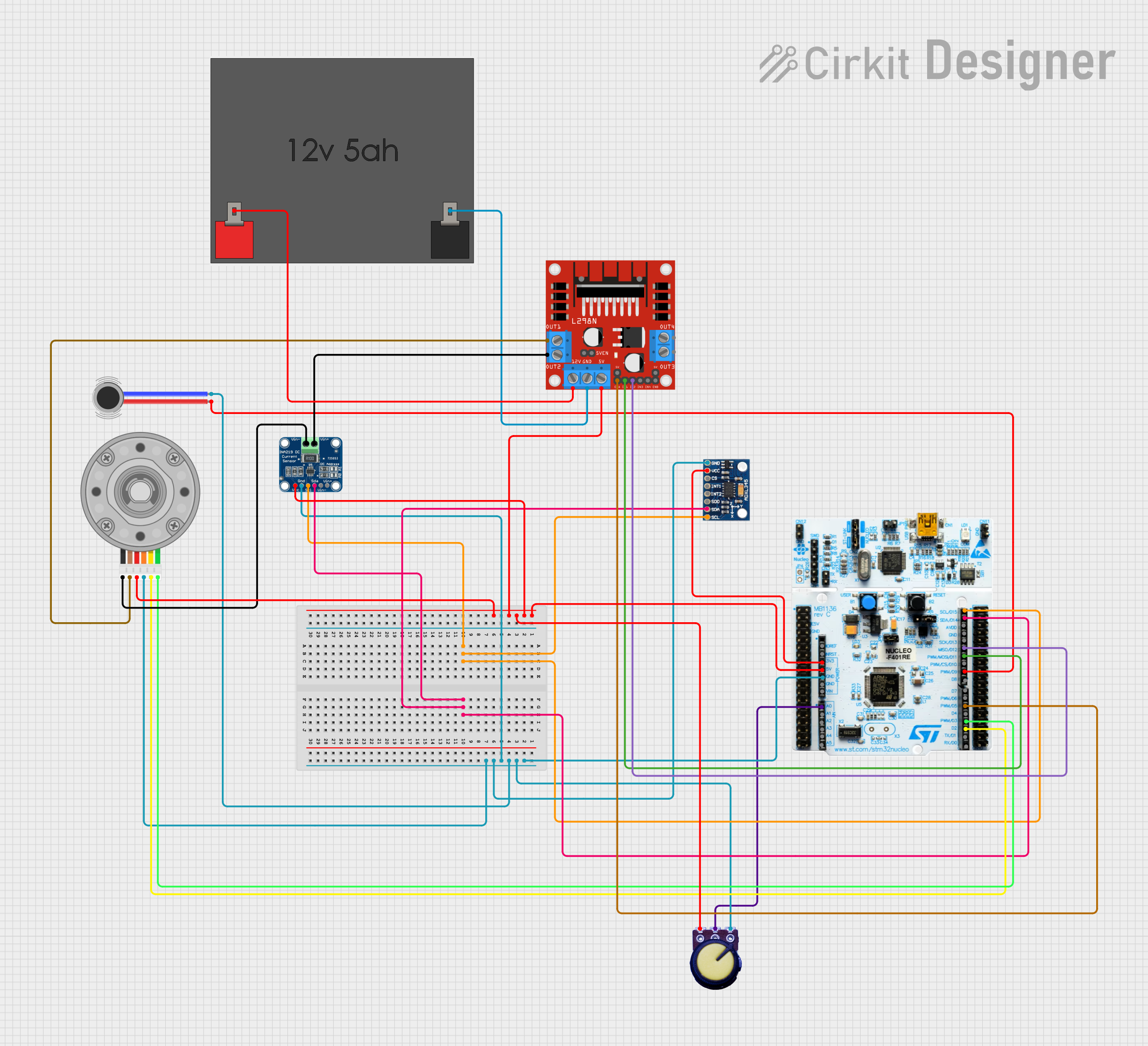 Open Project in Cirkit Designer
Explore Projects Built with PICAXE-28X1
Open Project in Cirkit DesignerOpen Project in Cirkit DesignerOpen Project in Cirkit DesignerOpen Project in Cirkit DesignerCommon Applications:
- Robotics and motor control
- Home automation systems
- Data acquisition and logging
- Educational tools for learning microcontroller programming
- Interactive art installations
Technical Specifications
The PICAXE-28X1 offers a range of features that make it suitable for a variety of projects. Below are its key technical details:
Key Technical Details:
- Microcontroller Core: Based on the Microchip PIC16F886
- Operating Voltage: 4.5V to 5.5V
- Clock Speed: 8 MHz (internal resonator)
- Programming Language: BASIC-like syntax
- I/O Pins:
- 16 digital I/O pins
- 4 analog input pins (10-bit resolution)
- EEPROM: 256 bytes
- RAM: 368 bytes
- Flash Memory: 4 KB (for user programs)
- Communication Protocols: Serial (RS232), I2C, SPI
- Power Consumption: Low-power operation with sleep modes
- Package Type: 28-pin DIP (Dual Inline Package)
Pin Configuration and Descriptions:
The PICAXE-28X1 has 28 pins, each with specific functions. Below is the pinout and description:
| Pin Number | Pin Name | Function |
|---|---|---|
| 1 | VSS | Ground (0V) |
| 2 | VDD | Power supply (4.5V to 5.5V) |
| 3 | Serial In | Serial programming input |
| 4 | Serial Out | Serial programming output |
| 5-12 | C.0 to C.7 | Digital I/O pins |
| 13-16 | B.0 to B.3 | Digital I/O pins |
| 17-20 | ADC0 to ADC3 | Analog inputs (10-bit resolution) |
| 21-28 | A.0 to A.7 | Digital I/O pins (some support PWM or SPI) |
Usage Instructions
The PICAXE-28X1 is easy to use and program, making it ideal for beginners. Below are the steps to get started and important considerations:
How to Use the PICAXE-28X1 in a Circuit:
- Power Supply: Connect the VDD pin to a 5V power source and the VSS pin to ground.
- Programming: Use a PICAXE programming cable to connect the Serial In and Serial Out pins to your computer. The PICAXE Editor software is required to write and upload code.
- I/O Connections:
- For digital I/O, connect devices (e.g., LEDs, switches) to the C, B, or A pins.
- For analog inputs, connect sensors to the ADC pins.
- Pull-Down Resistors: Use pull-down resistors on input pins to prevent floating states.
- External Components: Add decoupling capacitors (e.g., 0.1 µF) near the power pins to stabilize the power supply.
Example Code for Blinking an LED:
Below is an example program to blink an LED connected to pin C.0:
' Blink an LED connected to pin C.0
' The LED will turn on for 1 second and off for 1 second in a loop.

main:                ' Start of the main program loop
  high C.0           ' Turn on the LED (set pin C.0 high)
  pause 1000         ' Wait for 1 second (1000 ms)
  low C.0            ' Turn off the LED (set pin C.0 low)
  pause 1000         ' Wait for 1 second
  goto main          ' Repeat the loop
Important Considerations:
- Programming Cable: Ensure the correct orientation of the programming cable to avoid damaging the microcontroller.
- Power Supply: Use a regulated 5V power supply to prevent overvoltage damage.
- Pin Protection: Avoid exceeding the maximum current rating (25 mA per pin) to prevent damage.
- Decoupling Capacitors: Always use decoupling capacitors to reduce noise and improve stability.
Troubleshooting and FAQs
Common Issues and Solutions:
Microcontroller Not Responding:
- Cause: Incorrect wiring or power supply issues.
- Solution: Double-check all connections, ensure the power supply is within the specified range, and verify the programming cable is connected correctly.
Program Not Uploading:
- Cause: Incorrect COM port or programming cable not detected.
- Solution: Verify the correct COM port is selected in the PICAXE Editor. Ensure the programming cable drivers are installed.
Analog Readings Are Inaccurate:
- Cause: Noise or improper sensor connections.
- Solution: Use shielded cables for sensors and add decoupling capacitors near the ADC pins.
LED or Device Not Working:
- Cause: Incorrect pin configuration or insufficient current.
- Solution: Verify the pin mode (input/output) in the code and ensure the device is within the current limits.
FAQs:
Q: Can I use the PICAXE-28X1 with an Arduino?
- A: Yes, the PICAXE-28X1 can communicate with an Arduino via serial, I2C, or SPI protocols.
Q: What software is required to program the PICAXE-28X1?
- A: The PICAXE Editor, available for free on the official PICAXE website.
Q: Can I power the PICAXE-28X1 with batteries?
- A: Yes, you can use 4 AA batteries (6V) or a 5V regulated power supply.
Q: How do I reset the microcontroller?
- A: Disconnect and reconnect the power supply or use a reset button if included in your circuit.
This documentation provides a comprehensive guide to using the PICAXE-28X1 microcontroller effectively. Happy building!