How to Use SN74AHCT125 - Logics level converter: Examples, Pinouts, and Specs
Introduction
The SN74AHCT125 is a quad buffer/driver with 3-state outputs, designed for high-speed logic level conversion. It is commonly used to interface devices operating at different voltage levels, such as 3.3V and 5V logic systems. This component ensures reliable signal transmission while maintaining signal integrity, making it ideal for applications in microcontroller interfacing, digital communication, and mixed-voltage systems.
Explore Projects Built with SN74AHCT125 - Logics level converter


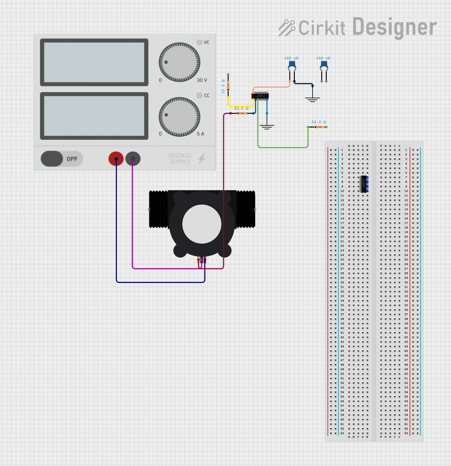

Explore Projects Built with SN74AHCT125 - Logics level converter
Common Applications:
- Voltage level shifting between 3.3V and 5V logic systems
- Signal buffering in digital circuits
- Microcontroller and peripheral interfacing
- Data communication in mixed-voltage environments
Technical Specifications
Key Technical Details:
- Operating Voltage Range: 4.5V to 5.5V
- Input Voltage Range: 0V to 5.5V
- Output Voltage Range: 0V to Vcc
- High-Level Output Current (IOH): -8mA
- Low-Level Output Current (IOL): 8mA
- Propagation Delay: 6ns (typical at 5V)
- 3-State Output Control: Enabled via an active-low OE (Output Enable) pin
- Operating Temperature Range: -40°C to 125°C
- Package Types: Available in SOIC, TSSOP, and PDIP packages
Pin Configuration and Descriptions:
The SN74AHCT125 has 14 pins, as shown in the table below:
| Pin Number | Pin Name | Description |
|---|---|---|
| 1 | OE1 | Output Enable for Buffer 1 (Active Low) |
| 2 | A1 | Input for Buffer 1 |
| 3 | Y1 | Output for Buffer 1 |
| 4 | OE2 | Output Enable for Buffer 2 (Active Low) |
| 5 | A2 | Input for Buffer 2 |
| 6 | Y2 | Output for Buffer 2 |
| 7 | GND | Ground |
| 8 | Y3 | Output for Buffer 3 |
| 9 | A3 | Input for Buffer 3 |
| 10 | OE3 | Output Enable for Buffer 3 (Active Low) |
| 11 | Y4 | Output for Buffer 4 |
| 12 | A4 | Input for Buffer 4 |
| 13 | OE4 | Output Enable for Buffer 4 (Active Low) |
| 14 | Vcc | Power Supply (4.5V to 5.5V) |
Usage Instructions
How to Use the SN74AHCT125 in a Circuit:
- Power Supply: Connect the Vcc pin to a 5V power source and the GND pin to ground.
- Input Signals: Apply the input signals to the A1, A2, A3, and A4 pins.
- Output Enable Control: Use the OE pins to enable or disable the corresponding outputs:
- When OE is LOW, the corresponding output (Y1, Y2, Y3, or Y4) is active.
- When OE is HIGH, the corresponding output is in a high-impedance (3-state) mode.
- Output Signals: The output signals (Y1, Y2, Y3, Y4) will follow the input signals (A1, A2, A3, A4) when the respective OE pin is LOW.
Important Considerations:
- Ensure that the input voltage levels are within the specified range (0V to 5.5V).
- Avoid leaving the OE pins floating; connect them to a defined logic level (HIGH or LOW).
- Decouple the power supply with a 0.1µF ceramic capacitor placed close to the Vcc pin to reduce noise.
Example: Interfacing with an Arduino UNO
The SN74AHCT125 can be used to shift logic levels between a 3.3V sensor and a 5V Arduino UNO. Below is an example circuit and Arduino code:
Circuit Setup:
- Connect the sensor's 3.3V output to A1.
- Connect Y1 to an Arduino UNO digital input pin (e.g., D2).
- Connect OE1 to GND to enable the output.
- Connect Vcc to the Arduino's 5V pin and GND to the Arduino's GND.
Arduino Code:
// Example code for reading a 3.3V sensor signal through SN74AHCT125
const int sensorPin = 2; // Arduino pin connected to Y1 (output of SN74AHCT125)

void setup() {
  pinMode(sensorPin, INPUT); // Set the sensor pin as input
  Serial.begin(9600);        // Initialize serial communication
}

void loop() {
  int sensorValue = digitalRead(sensorPin); // Read the sensor value
  Serial.println(sensorValue);             // Print the value to the Serial Monitor
  delay(500);                              // Wait for 500ms
}
Troubleshooting and FAQs
Common Issues:
No Output Signal:
- Cause: OE pin is not properly connected.
- Solution: Ensure the OE pin is connected to GND to enable the output.
Incorrect Voltage Levels:
- Cause: Vcc is not within the specified range (4.5V to 5.5V).
- Solution: Verify the power supply voltage and ensure it is within the acceptable range.
High Propagation Delay:
- Cause: Excessive capacitive load on the output pins.
- Solution: Minimize the load capacitance by using shorter traces and avoiding unnecessary components.
Output in High-Impedance State:
- Cause: OE pin is HIGH or floating.
- Solution: Pull the OE pin LOW to activate the output.
FAQs:
Q1: Can the SN74AHCT125 be used for bidirectional level shifting?
A1: No, the SN74AHCT125 is designed for unidirectional level shifting. For bidirectional level shifting, consider using a dedicated bidirectional level shifter.
Q2: What happens if the input voltage exceeds 5.5V?
A2: Applying a voltage higher than 5.5V to the input pins may damage the device. Always ensure the input voltage is within the specified range.
Q3: Can I use the SN74AHCT125 with a 3.3V power supply?
A3: No, the SN74AHCT125 requires a power supply voltage between 4.5V and 5.5V. For 3.3V systems, consider using a different logic level converter.
Q4: How do I connect unused inputs?
A4: Unused inputs should be tied to GND or Vcc to prevent floating inputs, which can cause unpredictable behavior.