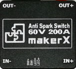
How to Use Anti Spark Switch: Examples, Pinouts, and Specs
Introduction
The Anti Spark Switch by MarkerX is a specialized electronic component designed to prevent electrical arcing when connecting or disconnecting circuits. Electrical arcing can cause damage to sensitive components, reduce the lifespan of connectors, and pose safety risks. This switch enhances safety and reliability in high-current applications by mitigating these issues.
Explore Projects Built with Anti Spark Switch

Explore Projects Built with Anti Spark Switch
Common Applications and Use Cases
- High-current battery systems (e.g., lithium-ion battery packs)
- Electric vehicles (EVs) and drones
- RC models and robotics
- Power supply systems for industrial equipment
- Protection of sensitive electronic components during power-up
Technical Specifications
The following table outlines the key technical details of the MarkerX Anti Spark Switch:
| Parameter | Value |
|---|---|
| Operating Voltage | 12V to 60V |
| Maximum Current | 150A (continuous), 200A (peak) |
| Power Consumption | < 0.5W |
| Switch Type | MOSFET-based |
| Trigger Mechanism | Push-button or external signal |
| Dimensions | 50mm x 30mm x 15mm |
| Weight | 25g |
| Operating Temperature | -20°C to 85°C |
Pin Configuration and Descriptions
The MarkerX Anti Spark Switch has the following pin configuration:
| Pin Name | Description |
|---|---|
| IN+ | Positive input terminal for the power source |
| IN- | Negative input terminal for the power source |
| OUT+ | Positive output terminal for the load |
| OUT- | Negative output terminal for the load |
| TRIG | Trigger pin for external control (e.g., microcontroller or push-button input) |
Usage Instructions
How to Use the Component in a Circuit
- Connect the Power Source:
- Attach the positive terminal of the power source to the
IN+pin. - Attach the negative terminal of the power source to the
IN-pin.
- Attach the positive terminal of the power source to the
- Connect the Load:
- Connect the positive terminal of the load to the
OUT+pin. - Connect the negative terminal of the load to the
OUT-pin.
- Connect the positive terminal of the load to the
- Trigger the Switch:
- Use the
TRIGpin to activate the switch. This can be done using a push-button or a signal from a microcontroller.
- Use the
Important Considerations and Best Practices
- Pre-charge Resistor: The switch includes an internal pre-charge resistor to limit inrush current during activation. Ensure the switch is triggered properly to avoid bypassing this feature.
- Heat Dissipation: For continuous high-current applications, ensure adequate ventilation or heat sinking to prevent overheating.
- Polarity: Double-check the polarity of the connections to avoid damage to the switch or connected components.
- External Control: If using a microcontroller (e.g., Arduino UNO) to control the switch, ensure the trigger signal voltage matches the
TRIGpin requirements.
Example: Using the Anti Spark Switch with an Arduino UNO
Below is an example of how to control the MarkerX Anti Spark Switch using an Arduino UNO:
// Example code to control the MarkerX Anti Spark Switch with an Arduino UNO
// This code assumes the TRIG pin of the switch is connected to Arduino pin 7.

const int triggerPin = 7; // Define the Arduino pin connected to the TRIG pin

void setup() {
  pinMode(triggerPin, OUTPUT); // Set the trigger pin as an output
  digitalWrite(triggerPin, LOW); // Ensure the switch is off at startup
}

void loop() {
  // Turn on the Anti Spark Switch
  digitalWrite(triggerPin, HIGH); // Send a HIGH signal to activate the switch
  delay(5000); // Keep the switch on for 5 seconds

  // Turn off the Anti Spark Switch
  digitalWrite(triggerPin, LOW); // Send a LOW signal to deactivate the switch
  delay(5000); // Keep the switch off for 5 seconds
}
Troubleshooting and FAQs
Common Issues and Solutions
The switch does not activate when triggered:
- Ensure the
TRIGpin is receiving the correct voltage level (e.g., 5V for Arduino). - Verify that the power source is properly connected to the
IN+andIN-pins. - Check for loose or faulty connections.
- Ensure the
Excessive heat during operation:
- Ensure the current does not exceed the maximum continuous rating of 150A.
- Add a heat sink or improve ventilation around the switch.
Arcing still occurs during connection:
- Verify that the switch is properly triggered before connecting the load.
- Check for damage to the internal pre-charge resistor.
The load does not receive power:
- Confirm that the
OUT+andOUT-pins are correctly connected to the load. - Test the load separately to ensure it is functioning properly.
- Confirm that the
FAQs
Q: Can the Anti Spark Switch handle voltages above 60V?
A: No, the switch is rated for a maximum operating voltage of 60V. Exceeding this limit may damage the component.
Q: Is the switch waterproof?
A: No, the switch is not waterproof. It should be used in a dry environment or enclosed in a protective casing.
Q: Can I use the switch with a 3.3V microcontroller?
A: Yes, but ensure the TRIG pin is compatible with the 3.3V logic level. If not, use a level shifter.
Q: Does the switch require an external pre-charge resistor?
A: No, the switch includes an internal pre-charge resistor to limit inrush current.
By following this documentation, you can safely and effectively integrate the MarkerX Anti Spark Switch into your projects.