How to Use Slit photocell: Examples, Pinouts, and Specs
Introduction
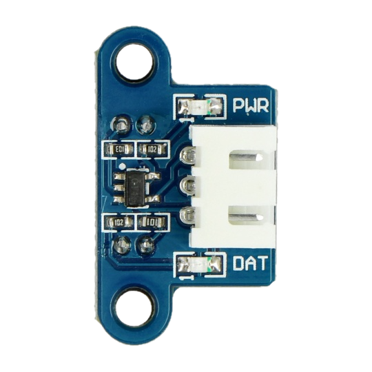
The Slit Photocell (Manufacturer: Waveshare, Part ID: 12225) is a light-sensitive device designed to detect the presence or absence of light through a narrow slit. This component is highly effective in applications requiring precise light detection, such as automatic lighting systems, safety devices, and optical encoders. Its ability to respond to changes in light intensity makes it a versatile tool for automation and control systems.
Explore Projects Built with Slit photocell
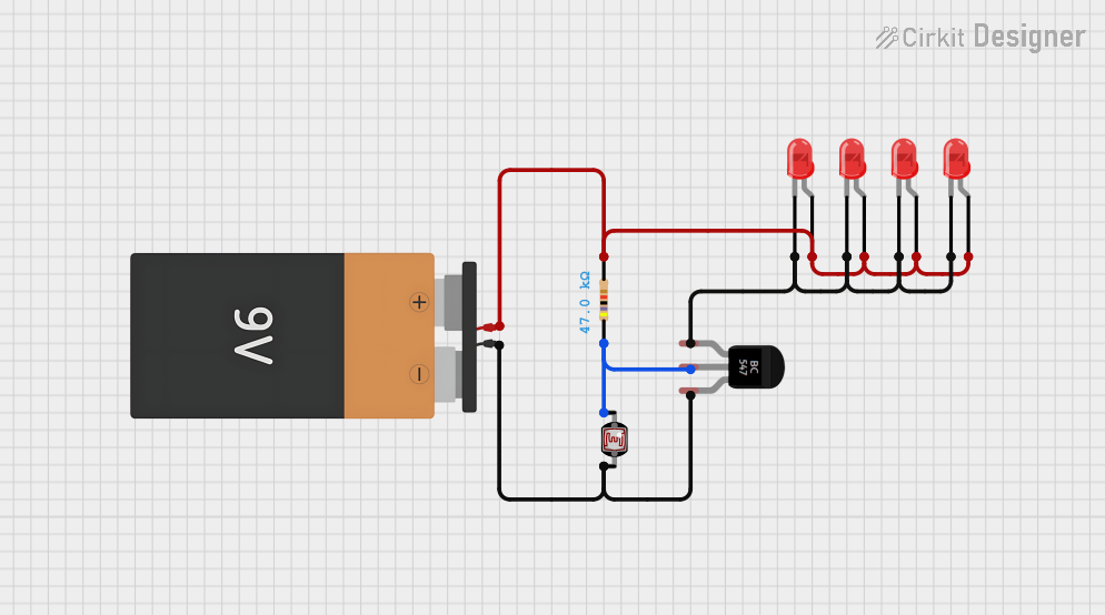
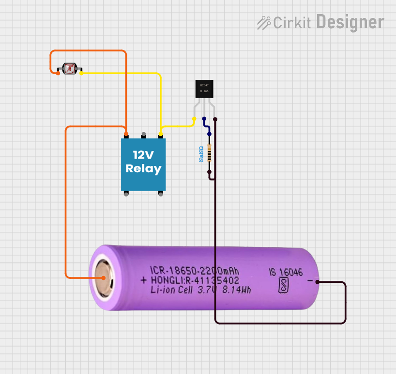
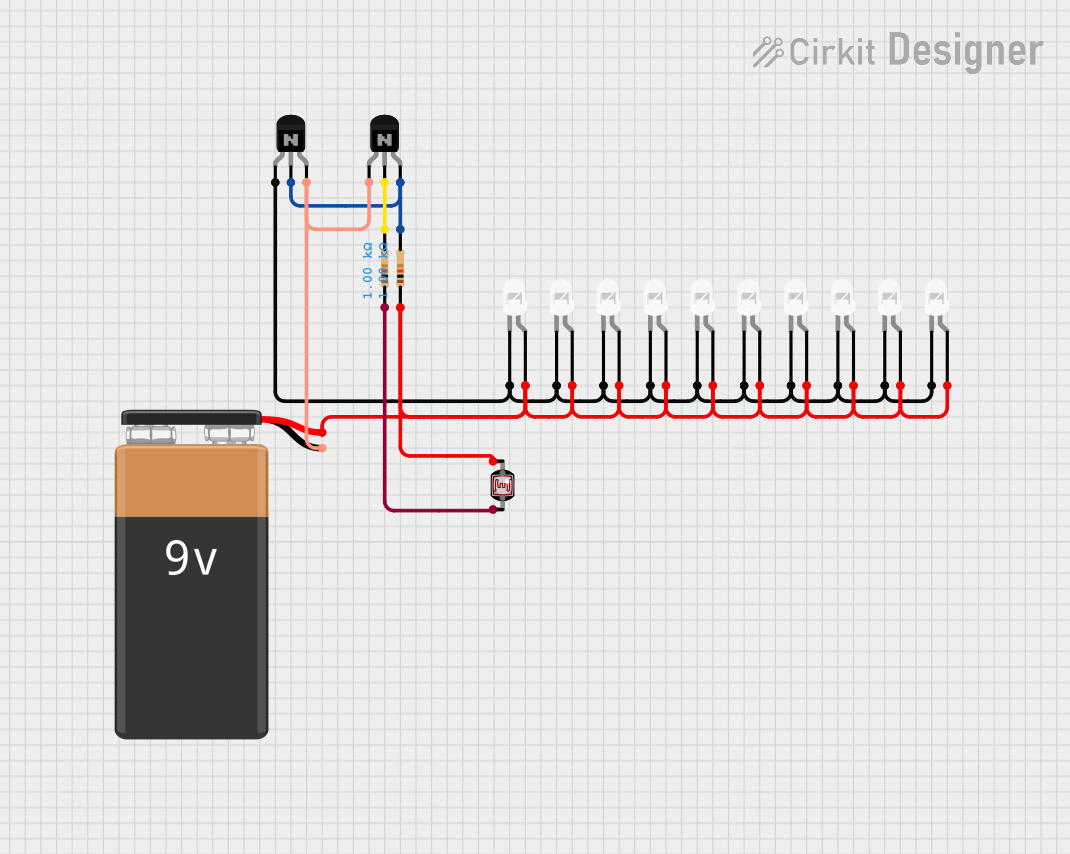
Explore Projects Built with Slit photocell
Common Applications
- Automatic Lighting Systems: Activates or deactivates lights based on ambient light levels.
- Safety Devices: Detects obstructions or changes in light for safety mechanisms.
- Optical Encoders: Measures position or motion by detecting light interruptions.
- Industrial Automation: Used in conveyor systems to detect objects passing through a slit.
Technical Specifications
The following table outlines the key technical details of the Waveshare Slit Photocell (Part ID: 12225):
| Parameter | Value |
|---|---|
| Operating Voltage | 3.3V to 5V |
| Operating Current | ≤ 20mA |
| Detection Range | 0.1mm to 5mm (through slit) |
| Response Time | ≤ 1ms |
| Output Type | Digital (High/Low) |
| Operating Temperature | -25°C to 85°C |
| Dimensions | 30mm x 15mm x 10mm |
Pin Configuration
The Slit Photocell has a 3-pin interface. The pinout is as follows:
| Pin | Name | Description |
|---|---|---|
| 1 | VCC | Power supply input (3.3V to 5V) |
| 2 | GND | Ground connection |
| 3 | OUT | Digital output signal (High when light is detected) |
Usage Instructions
Connecting the Slit Photocell
- Power Supply: Connect the VCC pin to a 3.3V or 5V power source and the GND pin to the ground of your circuit.
- Output Signal: Connect the OUT pin to a digital input pin of your microcontroller or logic circuit.
- Positioning: Ensure the slit is aligned with the light source or object to be detected. The detection range is optimal within 0.1mm to 5mm.
Example Circuit with Arduino UNO
Below is an example of how to connect and use the Slit Photocell with an Arduino UNO:
Circuit Connections
- VCC: Connect to the 5V pin on the Arduino.
- GND: Connect to the GND pin on the Arduino.
- OUT: Connect to digital pin 2 on the Arduino.
Arduino Code
// Slit Photocell Example with Arduino UNO
// This code reads the digital output of the slit photocell and prints the status
// to the Serial Monitor. The LED on pin 13 will turn on when light is detected.

const int photocellPin = 2;  // Digital pin connected to the OUT pin of the photocell
const int ledPin = 13;       // Built-in LED pin on Arduino

void setup() {
  pinMode(photocellPin, INPUT);  // Set photocell pin as input
  pinMode(ledPin, OUTPUT);      // Set LED pin as output
  Serial.begin(9600);           // Initialize serial communication
}

void loop() {
  int lightStatus = digitalRead(photocellPin);  // Read the photocell output

  if (lightStatus == HIGH) {
    // Light is detected
    digitalWrite(ledPin, HIGH);  // Turn on the LED
    Serial.println("Light detected!");
  } else {
    // No light detected
    digitalWrite(ledPin, LOW);   // Turn off the LED
    Serial.println("No light detected.");
  }

  delay(100);  // Small delay for stability
}
Best Practices
- Avoid Direct Sunlight: The slit photocell is sensitive to light intensity. Avoid placing it in direct sunlight to prevent false readings.
- Stable Power Supply: Use a stable power source to ensure consistent performance.
- Alignment: Properly align the slit with the light source or object for accurate detection.
- Debouncing: If the output signal fluctuates, consider adding a small capacitor or software debouncing.
Troubleshooting and FAQs
Common Issues and Solutions
No Output Signal
- Cause: Incorrect wiring or insufficient power supply.
- Solution: Double-check the connections and ensure the power supply is within the specified range (3.3V to 5V).
False Readings
- Cause: Ambient light interference or misalignment.
- Solution: Shield the slit photocell from ambient light and ensure proper alignment with the light source.
Slow Response
- Cause: Excessive capacitance in the circuit.
- Solution: Remove any unnecessary capacitors or reduce the capacitance value.
Output Always High or Low
- Cause: Damaged component or incorrect positioning.
- Solution: Test the component with a multimeter and verify the slit is unobstructed.
FAQs
Q: Can the slit photocell detect objects in complete darkness?
A: No, the slit photocell requires a light source to detect objects. It works by sensing interruptions in the light passing through the slit.
Q: What is the maximum detection range?
A: The slit photocell can detect light interruptions within a range of 0.1mm to 5mm.
Q: Can I use the slit photocell with a 3.3V microcontroller?
A: Yes, the slit photocell operates within a voltage range of 3.3V to 5V, making it compatible with 3.3V microcontrollers.
Q: How do I clean the slit if it gets dirty?
A: Use a soft, lint-free cloth or compressed air to gently clean the slit. Avoid using liquids or abrasive materials.
By following this documentation, you can effectively integrate the Waveshare Slit Photocell (Part ID: 12225) into your projects for reliable light detection and automation.