How to Use splicing connector 2: Examples, Pinouts, and Specs
Introduction
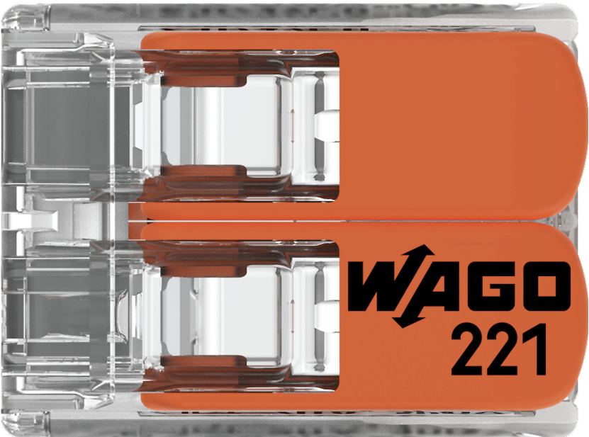
The Splicing Connector 2 by WAGO is a compact and reliable electrical connector designed to join two or more electrical wires or cables. It ensures a secure and durable connection, making it ideal for both low-voltage and high-voltage applications. This connector is widely used in electrical installations, industrial automation, and DIY projects due to its ease of use and robust design.
Explore Projects Built with splicing connector 2


Explore Projects Built with splicing connector 2
Common Applications and Use Cases
- Electrical wiring in residential, commercial, and industrial environments
- Connecting wires in control panels and distribution boxes
- DIY electronics and prototyping projects
- Signal transmission in low-voltage circuits
- Temporary or permanent wire splicing in automotive and machinery repairs
Technical Specifications
The following table outlines the key technical details of the Splicing Connector 2:
| Parameter | Specification |
|---|---|
| Manufacturer | WAGO |
| Part ID | Splicing Connector |
| Number of Connections | 2 |
| Wire Size Compatibility | 28–12 AWG (0.08–4 mm²) |
| Voltage Rating | 450 V AC |
| Current Rating | 32 A |
| Operating Temperature | -40°C to +105°C |
| Housing Material | Polycarbonate (PC), flame-retardant |
| Connection Type | Push-in spring technology |
| Dimensions (L x W x H) | 20.5 mm x 13.1 mm x 8.3 mm |
| Certifications | UL, CE, RoHS compliant |
Pin Configuration and Descriptions
The Splicing Connector 2 does not have traditional pins but instead features two wire entry points. The table below describes the wire entry points:
| Entry Point | Description |
|---|---|
| Entry Point 1 | Insert the first wire here. Compatible with solid, stranded, or fine-stranded wires. |
| Entry Point 2 | Insert the second wire here. Ensures a secure connection with the first wire. |
Usage Instructions
How to Use the Splicing Connector 2 in a Circuit
- Prepare the Wires: Strip approximately 10–12 mm of insulation from the ends of the wires you want to connect.
- Open the Connector: If the connector has a lever, lift it to open the wire entry points.
- Insert the Wires: Push the stripped ends of the wires into the respective entry points until they are fully seated.
- Secure the Connection: Close the lever (if applicable) to lock the wires in place. For push-in connectors, ensure the wires are firmly inserted.
- Verify the Connection: Gently tug on the wires to confirm they are securely held in place.
Important Considerations and Best Practices
- Ensure the wire size is within the specified range (28–12 AWG) for optimal performance.
- Avoid over-stripping the wires, as this may expose excess conductor and increase the risk of short circuits.
- Use the connector only within its rated voltage (450 V AC) and current (32 A) limits.
- For high-vibration environments, double-check the wire connections to prevent accidental disconnection.
- Store the connectors in a dry, dust-free environment to maintain their integrity.
Example: Connecting to an Arduino UNO
While the Splicing Connector 2 is not directly programmable, it can be used to connect wires from sensors or actuators to an Arduino UNO. Below is an example of wiring a temperature sensor to an Arduino using the splicing connector:
// Example: Reading temperature data from a sensor connected via Splicing Connector 2
// Ensure proper wire connections using the splicing connector for secure signal transmission.

const int sensorPin = A0; // Analog pin connected to the temperature sensor
int sensorValue = 0;      // Variable to store the sensor reading

void setup() {
  Serial.begin(9600); // Initialize serial communication at 9600 baud
}

void loop() {
  sensorValue = analogRead(sensorPin); // Read the sensor value
  float voltage = sensorValue * (5.0 / 1023.0); // Convert to voltage
  Serial.print("Sensor Voltage: ");
  Serial.println(voltage); // Print the voltage to the Serial Monitor
  delay(1000); // Wait for 1 second before the next reading
}
Troubleshooting and FAQs
Common Issues Users Might Face
Loose Connections:
- Cause: Wires not fully inserted or improperly stripped.
- Solution: Ensure wires are stripped to the correct length (10–12 mm) and fully seated in the connector.
Overheating:
- Cause: Exceeding the current or voltage rating of the connector.
- Solution: Verify that the connected circuit does not exceed 32 A or 450 V AC.
Wire Slippage:
- Cause: Using wires outside the specified size range (28–12 AWG).
- Solution: Use only compatible wire sizes and check the connection after insertion.
Connector Damage:
- Cause: Excessive force during wire insertion or removal.
- Solution: Handle the connector gently and avoid using tools that may damage the housing.
FAQs
Q1: Can the Splicing Connector 2 be reused?
A1: Yes, the connector can be reused. Simply remove the wires by pulling them out gently while lifting the lever (if applicable).
Q2: Is the connector suitable for outdoor use?
A2: The connector is not waterproof. For outdoor applications, use a weatherproof enclosure to protect it from moisture and dust.
Q3: Can stranded and solid wires be mixed in the same connector?
A3: Yes, the connector supports both stranded and solid wires, even in the same connection.
Q4: How many wires can be connected using the Splicing Connector 2?
A4: This specific model supports two wires. For more connections, consider using a larger splicing connector model.
By following this documentation, users can confidently and effectively use the Splicing Connector 2 in their electrical and electronic projects.