Cirkit Designer Logo
Cirkit Designer
Your all-in-one circuit design IDE
Home / 
Component Documentation

How to Use Adafruit Thermocouple Amplifier with 1-Wire Breakout Board - MAX31850K: Examples, Pinouts, and Specs

Image of Adafruit Thermocouple Amplifier with 1-Wire Breakout Board - MAX31850K
Cirkit Designer LogoDesign with Adafruit Thermocouple Amplifier with 1-Wire Breakout Board - MAX31850K in Cirkit Designer

Introduction

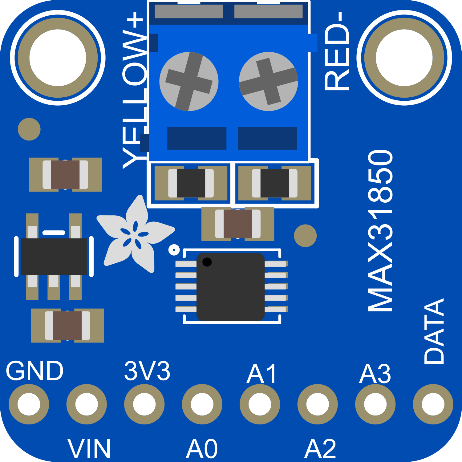
The Adafruit Thermocouple Amplifier with 1-Wire Breakout Board featuring the MAX31850K is a sophisticated electronic component designed to interface with thermocouple sensors, providing precise temperature measurements. This breakout board simplifies the process of reading temperatures from a K-type thermocouple and communicates the data over a 1-Wire interface, which is ideal for microcontroller-based projects.

Explore Projects Built with Adafruit Thermocouple Amplifier with 1-Wire Breakout Board - MAX31850K

Use Cirkit Designer to design, explore, and prototype these projects online. Some projects support real-time simulation. Click "Open Project" to start designing instantly!
Arduino Nano Temperature Logger with TFT Display and RTC
Image of Nils: A project utilizing Adafruit Thermocouple Amplifier with 1-Wire Breakout Board - MAX31850K in a practical application
This circuit uses an Arduino Nano to read temperature data from a MAX31865 thermocouple amplifier connected to a PT100 sensor, display the temperature on a round TFT screen, and log the data with timestamps using a DS3231 RTC. A momentary switch is used to control the logging and display a temperature graph on the TFT screen.
Cirkit Designer LogoOpen Project in Cirkit Designer
Arduino Mega 2560-Based Temperature-Controlled Valve, Pump, and Fan System with SD Card Logging
Image of wiring arduinomega: A project utilizing Adafruit Thermocouple Amplifier with 1-Wire Breakout Board - MAX31850K in a practical application
This circuit is a temperature monitoring and control system using an Arduino Mega 2560, multiple thermocouple amplifiers, and a current sensor. It controls a valve, pump, and fan via relays based on temperature readings, and logs the data to an SD card.
Cirkit Designer LogoOpen Project in Cirkit Designer
Arduino Mega 2560 Based Multi-Channel Thermocouple Reader
Image of thermostat-test: A project utilizing Adafruit Thermocouple Amplifier with 1-Wire Breakout Board - MAX31850K in a practical application
This circuit is designed to interface with multiple MAX6675 thermocouple-to-digital converter modules using an Arduino Mega 2560 as the central processing unit. The Arduino reads temperature data from the MAX6675 modules over a shared SPI bus, with individual chip select (CS) lines for each module to enable multiplexing. The circuit is likely used for monitoring multiple temperature points, possibly in an industrial setting where precise temperature control and monitoring are critical.
Cirkit Designer LogoOpen Project in Cirkit Designer
Arduino UNO and MAX31865 RTD Sensor Temperature Monitoring System
Image of PT100: A project utilizing Adafruit Thermocouple Amplifier with 1-Wire Breakout Board - MAX31850K in a practical application
This circuit involves an Arduino UNO microcontroller interfaced with three Adafruit MAX31865 RTD Sensor Breakout boards. The Arduino controls the sensors via SPI communication to measure temperature data from RTD sensors, with each sensor's chip select (CS) pin connected to a different digital pin on the Arduino.
Cirkit Designer LogoOpen Project in Cirkit Designer

Explore Projects Built with Adafruit Thermocouple Amplifier with 1-Wire Breakout Board - MAX31850K

Use Cirkit Designer to design, explore, and prototype these projects online. Some projects support real-time simulation. Click "Open Project" to start designing instantly!
Image of Nils: A project utilizing Adafruit Thermocouple Amplifier with 1-Wire Breakout Board - MAX31850K in a practical application
Arduino Nano Temperature Logger with TFT Display and RTC
This circuit uses an Arduino Nano to read temperature data from a MAX31865 thermocouple amplifier connected to a PT100 sensor, display the temperature on a round TFT screen, and log the data with timestamps using a DS3231 RTC. A momentary switch is used to control the logging and display a temperature graph on the TFT screen.
Cirkit Designer LogoOpen Project in Cirkit Designer
Image of wiring arduinomega: A project utilizing Adafruit Thermocouple Amplifier with 1-Wire Breakout Board - MAX31850K in a practical application
Arduino Mega 2560-Based Temperature-Controlled Valve, Pump, and Fan System with SD Card Logging
This circuit is a temperature monitoring and control system using an Arduino Mega 2560, multiple thermocouple amplifiers, and a current sensor. It controls a valve, pump, and fan via relays based on temperature readings, and logs the data to an SD card.
Cirkit Designer LogoOpen Project in Cirkit Designer
Image of thermostat-test: A project utilizing Adafruit Thermocouple Amplifier with 1-Wire Breakout Board - MAX31850K in a practical application
Arduino Mega 2560 Based Multi-Channel Thermocouple Reader
This circuit is designed to interface with multiple MAX6675 thermocouple-to-digital converter modules using an Arduino Mega 2560 as the central processing unit. The Arduino reads temperature data from the MAX6675 modules over a shared SPI bus, with individual chip select (CS) lines for each module to enable multiplexing. The circuit is likely used for monitoring multiple temperature points, possibly in an industrial setting where precise temperature control and monitoring are critical.
Cirkit Designer LogoOpen Project in Cirkit Designer
Image of PT100: A project utilizing Adafruit Thermocouple Amplifier with 1-Wire Breakout Board - MAX31850K in a practical application
Arduino UNO and MAX31865 RTD Sensor Temperature Monitoring System
This circuit involves an Arduino UNO microcontroller interfaced with three Adafruit MAX31865 RTD Sensor Breakout boards. The Arduino controls the sensors via SPI communication to measure temperature data from RTD sensors, with each sensor's chip select (CS) pin connected to a different digital pin on the Arduino.
Cirkit Designer LogoOpen Project in Cirkit Designer

Common Applications and Use Cases

  • Industrial temperature monitoring
  • High-temperature measurement in ovens and kilns
  • Home brewing and cooking appliances
  • HVAC systems and refrigeration
  • Laboratory and scientific equipment

Technical Specifications

Key Technical Details

  • Operating Voltage: 3.3V to 5V
  • Temperature Resolution: 0.25°C
  • Temperature Range: -270°C to +1768°C (K-type)
  • Interface: 1-Wire

Pin Configuration and Descriptions

Pin Number Name Description
1 GND Ground connection
2 VDD Power supply (3.3V to 5V)
3 DQ 1-Wire Data line
4 NC No connection (reserved for future use)

Usage Instructions

How to Use the Component in a Circuit

  1. Connect the GND pin to the ground of your power supply.
  2. Connect the VDD pin to a 3.3V or 5V power supply.
  3. Connect the DQ pin to a digital input/output pin on your microcontroller.
  4. Attach a K-type thermocouple to the input terminals of the breakout board.

Important Considerations and Best Practices

  • Ensure that the thermocouple wires are connected correctly: the red wire is typically the negative lead, and the yellow or other color wire is the positive lead.
  • Use a pull-up resistor (typically 4.7kΩ) on the DQ line when connecting to a microcontroller.
  • Keep the thermocouple and breakout board away from electrical noise sources to prevent inaccurate readings.
  • Avoid running the thermocouple wires parallel to high-current carrying conductors.

Example Code for Arduino UNO

#include <OneWire.h>
#include <DallasTemperature.h>

// Data wire is connected to pin 2 on the Arduino
#define ONE_WIRE_BUS 2

// Setup a oneWire instance to communicate with any OneWire devices
OneWire oneWire(ONE_WIRE_BUS);

// Pass our oneWire reference to Dallas Temperature sensor 
DallasTemperature sensors(&oneWire);

void setup(void) {
  // Start serial communication for debugging
  Serial.begin(9600);
  // Start up the library
  sensors.begin();
}

void loop(void) { 
  // Request temperature measurements
  sensors.requestTemperatures(); 
  // Fetch and print the temperature in Celsius
  Serial.print("Temperature: ");
  Serial.print(sensors.getTempCByIndex(0));
  Serial.println("°C");
  // Add a delay between measurements
  delay(1000);
}

Troubleshooting and FAQs

Common Issues Users Might Face

  • Inaccurate Temperature Readings: Ensure that the thermocouple is properly connected and not subject to electrical interference.
  • No Data on Serial Monitor: Check the wiring and ensure that the correct pin is used for the 1-Wire interface.
  • Fluctuating Readings: Ensure that there is a stable power supply and that the breakout board is not near high-current devices.

Solutions and Tips for Troubleshooting

  • Double-check the wiring against the pin configuration table.
  • Use twisted pair wires for the thermocouple to minimize interference.
  • Ensure that the Arduino library for the MAX31850K is correctly installed and included in your sketch.
  • Use the example code provided as a starting point and modify it according to your setup.

FAQs

Q: Can I use this breakout board with other types of thermocouples?

A: The MAX31850K is specifically designed for K-type thermocouples, so using other types may not provide accurate readings.

Q: How many of these breakout boards can I connect to a single microcontroller?

A: You can connect multiple boards to a single 1-Wire bus, but each device must have a unique address. The 1-Wire protocol supports device discovery, so you can daisy-chain several devices on the same wire.

Q: What is the maximum length for the thermocouple wires?

A: The maximum length depends on the wire gauge and the environment, but it's generally recommended to keep the wires as short as possible to prevent signal degradation and interference.