
How to Use Resettable Fuse PTC: Examples, Pinouts, and Specs

 Design with Resettable Fuse PTC in Cirkit Designer
Introduction
A resettable fuse, also known as a polymeric positive temperature coefficient (PTC) device, is a protective component designed to limit current flow in a circuit. When the current exceeds a predefined threshold, the fuse heats up and its resistance increases significantly, effectively shutting off the current. Once the fault condition is resolved and the device cools down, it resets automatically, allowing the circuit to resume normal operation.
Explore Projects Built with Resettable Fuse PTC
 Open Project in Cirkit Designer
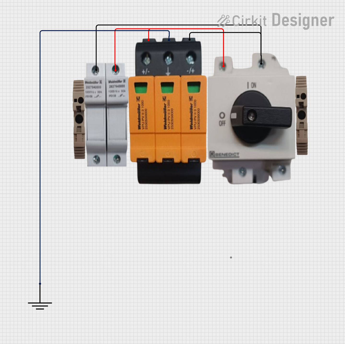 Open Project in Cirkit Designer
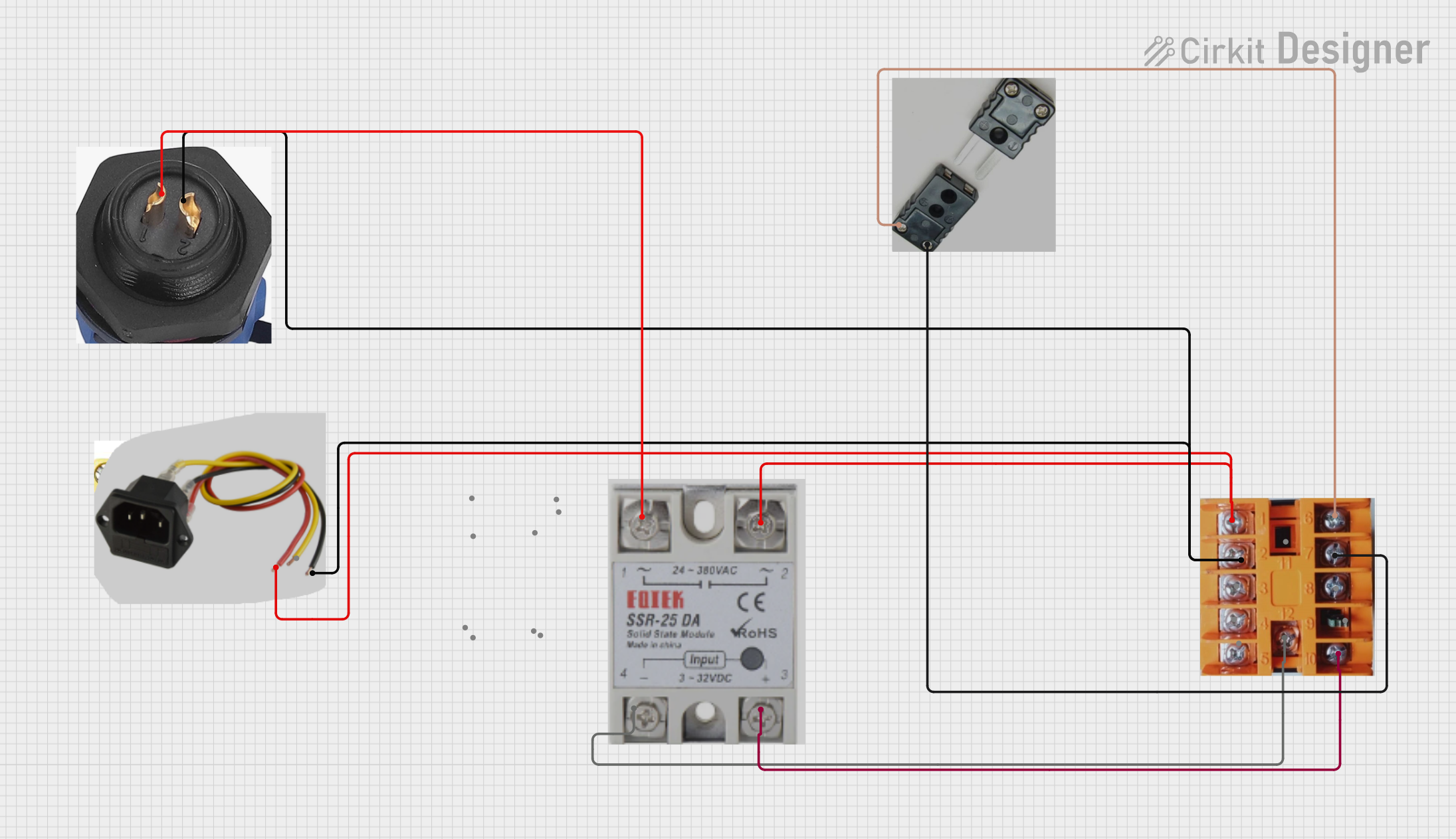 Open Project in Cirkit Designer
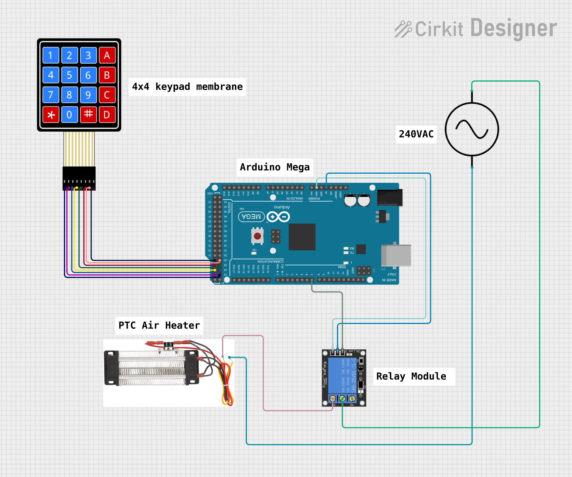 Open Project in Cirkit Designer
Explore Projects Built with Resettable Fuse PTC
Open Project in Cirkit DesignerOpen Project in Cirkit DesignerOpen Project in Cirkit DesignerOpen Project in Cirkit DesignerCommon Applications and Use Cases
- Overcurrent protection in power supplies and battery packs
- Protection for USB ports and peripheral devices
- Circuit protection in telecommunications equipment
- Automotive electronics to safeguard against short circuits
- Consumer electronics such as laptops, chargers, and gaming consoles
Technical Specifications
Key Technical Details
- Operating Voltage Range: Typically 6V to 60V (varies by model)
- Hold Current (IHOLD): 0.1A to 14A (depending on the specific PTC model)
- Trip Current (ITRIP): 2x to 3x the hold current
- Maximum Voltage (VMAX): 60V (varies by model)
- Resistance (RMIN to RMAX): 0.01Ω to 10Ω
- Operating Temperature: -40°C to +85°C
- Reset Time: Typically a few seconds to minutes, depending on the fault condition and cooling
Pin Configuration and Descriptions
Resettable fuses are typically two-terminal devices. Below is a general description of the pins:
| Pin Number | Pin Name | Description |
|---|---|---|
| 1 | Terminal 1 | Connects to the power source or load |
| 2 | Terminal 2 | Connects to the circuit to be protected |
Usage Instructions
How to Use the Component in a Circuit
Determine the Required Specifications:
- Identify the operating voltage and current of your circuit.
- Select a PTC fuse with a hold current (IHOLD) slightly higher than the normal operating current of your circuit.
- Ensure the trip current (ITRIP) is below the maximum current your circuit can tolerate.
Placement in the Circuit:
- Place the PTC fuse in series with the load or circuit you want to protect.
- Ensure proper orientation of the terminals (though PTC fuses are non-polarized).
Soldering and Mounting:
- Solder the PTC fuse onto the PCB or connect it securely using terminals.
- Avoid excessive heat during soldering to prevent damage to the component.
Testing:
- Power on the circuit and verify normal operation.
- Simulate an overcurrent condition to ensure the PTC fuse trips and resets as expected.
Important Considerations and Best Practices
- Derating: Always derate the hold current by 20-30% to account for temperature variations and aging.
- Thermal Management: Ensure adequate ventilation or heat dissipation to prevent prolonged tripping.
- Reset Time: Allow sufficient time for the PTC fuse to cool and reset after a fault condition.
- Parallel Connections: Avoid connecting multiple PTC fuses in parallel, as they may not trip simultaneously.
Example: Using a Resettable Fuse with an Arduino UNO
Below is an example of how to use a resettable fuse to protect an Arduino UNO from overcurrent:
Circuit Setup
- Connect the PTC fuse in series with the 5V power supply line to the Arduino UNO.
- Ensure the PTC fuse's hold current is slightly higher than the Arduino's typical operating current (e.g., 0.5A).
Code Example
// Example code to demonstrate normal operation of an Arduino UNO
// protected by a resettable fuse in case of overcurrent conditions.

void setup() {
  pinMode(13, OUTPUT); // Set pin 13 as an output (connected to an LED)
}

void loop() {
  digitalWrite(13, HIGH); // Turn the LED on
  delay(1000);            // Wait for 1 second
  digitalWrite(13, LOW);  // Turn the LED off
  delay(1000);            // Wait for 1 second
}

// Note: If an overcurrent condition occurs, the PTC fuse will trip,
// cutting off power to the Arduino. Once the fault is cleared and
// the fuse resets, the Arduino will resume normal operation.
Troubleshooting and FAQs
Common Issues and Solutions
PTC Fuse Does Not Reset:
- Cause: The fuse may still be hot or the fault condition persists.
- Solution: Allow more time for the fuse to cool down. Check for and resolve any short circuits or overcurrent conditions.
Frequent Tripping:
- Cause: The hold current of the PTC fuse is too close to the circuit's normal operating current.
- Solution: Replace the PTC fuse with one that has a higher hold current.
High Resistance After Reset:
- Cause: The PTC fuse may have degraded due to repeated tripping.
- Solution: Replace the PTC fuse with a new one.
Fuse Does Not Trip During Overcurrent:
- Cause: The trip current is too high for the fault condition.
- Solution: Use a PTC fuse with a lower trip current.
FAQs
Q1: Can a resettable fuse be used in AC circuits?
A1: Yes, resettable fuses can be used in AC circuits, but ensure the voltage and current ratings are suitable for the application.
Q2: How many times can a resettable fuse trip and reset?
A2: Most PTC fuses can trip and reset hundreds to thousands of times, depending on the operating conditions and the severity of the faults.
Q3: Can I use a resettable fuse to protect a motor?
A3: Yes, but ensure the inrush current of the motor does not exceed the trip current of the PTC fuse.
Q4: What happens if I exceed the maximum voltage rating of the PTC fuse?
A4: Exceeding the voltage rating can damage the PTC fuse and compromise its protective function. Always stay within the specified voltage range.