How to Use Bus PCB2: Examples, Pinouts, and Specs
Introduction
The Bus PCB2 is a printed circuit board designed to facilitate the connection and communication between multiple electronic components. It serves as a backbone for managing data and power distribution in complex systems, ensuring efficient and organized signal routing. This component is commonly used in applications such as embedded systems, industrial automation, robotics, and IoT devices, where multiple modules or subsystems need to communicate seamlessly.
Explore Projects Built with Bus PCB2


Explore Projects Built with Bus PCB2
Common Applications:
- Data and power distribution in embedded systems
- Signal routing in robotics and automation
- Communication backbones in IoT devices
- Modular electronic systems requiring centralized connectivity
Technical Specifications
Key Technical Details:
- Operating Voltage: 3.3V to 5V
- Maximum Current Capacity: 2A per bus line
- Number of Bus Lines: 8 (4 for data, 4 for power/ground)
- PCB Dimensions: 50mm x 50mm
- Connector Type: Standard 2.54mm pitch headers
- Supported Protocols: I2C, SPI, UART (dependent on connected components)
- Material: FR4 with 1oz copper thickness
- Operating Temperature Range: -40°C to 85°C
Pin Configuration and Descriptions:
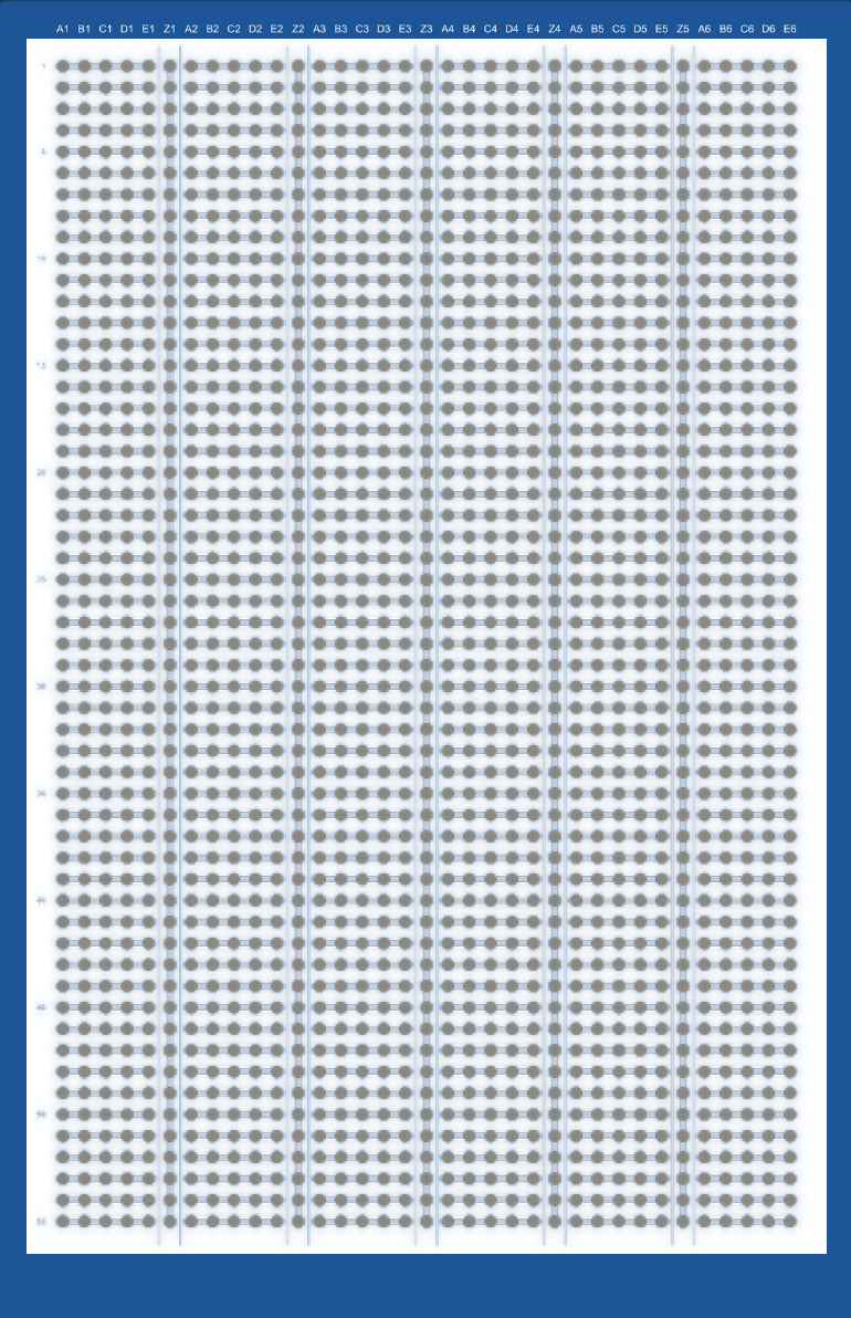
The Bus PCB2 features a standard 2x8 header configuration for easy integration with other components. Below is the pinout description:
| Pin Number | Label | Description |
|---|---|---|
| 1 | VCC | Power supply input (3.3V or 5V) |
| 2 | GND | Ground connection |
| 3 | DATA1 | Data line 1 for communication |
| 4 | DATA2 | Data line 2 for communication |
| 5 | DATA3 | Data line 3 for communication |
| 6 | DATA4 | Data line 4 for communication |
| 7 | PWR1 | Power output line 1 |
| 8 | PWR2 | Power output line 2 |
| 9 | PWR3 | Power output line 3 |
| 10 | PWR4 | Power output line 4 |
| 11 | NC | Not connected (reserved for future use) |
| 12 | NC | Not connected (reserved for future use) |
| 13 | CLK | Clock signal for synchronous protocols |
| 14 | RESET | Reset signal for connected devices |
| 15 | SDA | I2C data line |
| 16 | SCL | I2C clock line |
Usage Instructions
How to Use the Bus PCB2 in a Circuit:
Power Supply Connection:
- Connect the VCC pin to a regulated 3.3V or 5V power source.
- Connect the GND pin to the ground of your circuit.
Data Communication:
- Use the DATA1 to DATA4 pins for general-purpose data communication.
- For I2C communication, connect the SDA and SCL pins to the corresponding pins on your microcontroller.
- For SPI communication, use DATA1 (MOSI), DATA2 (MISO), and CLK for the clock signal.
Power Distribution:
- Use the PWR1 to PWR4 pins to distribute power to connected modules or devices.
Reset and Clock Signals:
- If required, connect the RESET pin to the reset input of your devices.
- Use the CLK pin for synchronous communication protocols.
Important Considerations:
- Ensure that the total current drawn by connected devices does not exceed the maximum current capacity of 2A per bus line.
- Use appropriate decoupling capacitors near the power input to minimize noise and voltage fluctuations.
- Verify the voltage levels of connected devices to ensure compatibility with the Bus PCB2.
Example: Connecting Bus PCB2 to an Arduino UNO
Below is an example of how to connect the Bus PCB2 to an Arduino UNO for I2C communication:
Circuit Connections:
- Connect VCC on the Bus PCB2 to the 5V pin on the Arduino UNO.
- Connect GND on the Bus PCB2 to the GND pin on the Arduino UNO.
- Connect SDA on the Bus PCB2 to the A4 pin on the Arduino UNO.
- Connect SCL on the Bus PCB2 to the A5 pin on the Arduino UNO.
Arduino Code Example:
#include <Wire.h> // Include the Wire library for I2C communication

void setup() {
  Wire.begin(); // Initialize I2C communication
  Serial.begin(9600); // Start serial communication for debugging
  Serial.println("Bus PCB2 I2C Communication Initialized");
}

void loop() {
  Wire.beginTransmission(0x08); // Start communication with device at address 0x08
  Wire.write("Hello, Bus PCB2!"); // Send data to the device
  Wire.endTransmission(); // End the transmission

  delay(1000); // Wait for 1 second before sending the next message
}
Best Practices:
- Use short and properly shielded wires to minimize signal interference.
- Label the connections on your Bus PCB2 to avoid wiring errors.
- Regularly inspect the PCB for any signs of damage or wear.
Troubleshooting and FAQs
Common Issues:
No Power to Connected Devices:
- Cause: Incorrect connection to the VCC or GND pins.
- Solution: Double-check the power supply connections and ensure the voltage matches the requirements.
Communication Failure:
- Cause: Incorrect wiring of data lines or mismatched protocols.
- Solution: Verify the connections and ensure the correct protocol (I2C, SPI, etc.) is being used.
Overheating:
- Cause: Excessive current draw from connected devices.
- Solution: Ensure the total current does not exceed 2A per bus line. Use external power supplies if needed.
Signal Interference:
- Cause: Long or unshielded wires.
- Solution: Use shorter wires and consider adding ferrite beads or shielding.
FAQs:
Q: Can the Bus PCB2 handle 12V power?
A: No, the Bus PCB2 is designed for 3.3V to 5V operation. Using 12V may damage the board.Q: Can I use the Bus PCB2 for analog signals?
A: Yes, but ensure the signal levels are within the supported voltage range (3.3V to 5V).Q: How many devices can I connect to the Bus PCB2?
A: The number of devices depends on the current requirements and communication protocol. For I2C, ensure each device has a unique address.
By following this documentation, you can effectively integrate the Bus PCB2 into your projects and troubleshoot any issues that arise.