How to Use DSN6000AUD DC-DC: Examples, Pinouts, and Specs
Introduction
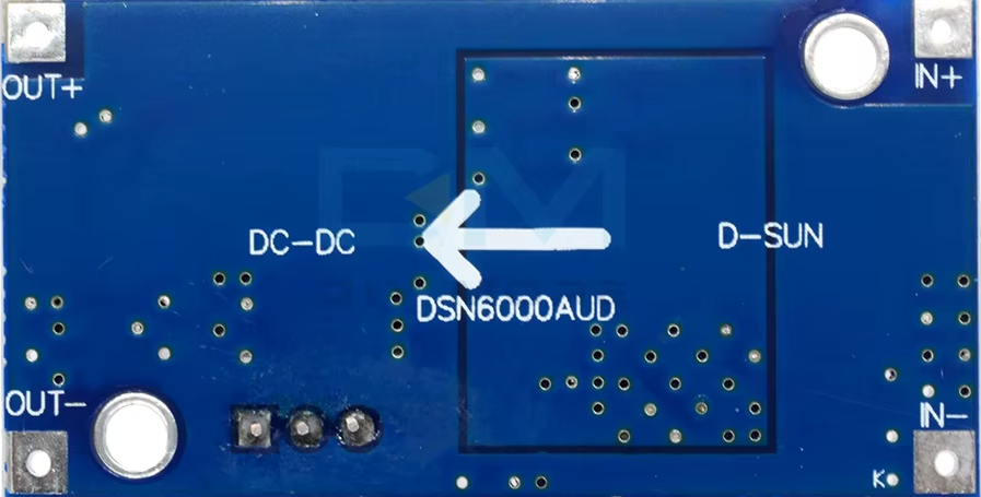
The DSN6000AUD DC-DC Step-Up Step-Down Converter Module, manufactured by Zhejiang, is a compact and versatile power management solution. This module is designed to efficiently convert input voltage to a stable output voltage, regardless of whether the input voltage is higher or lower than the desired output. Its high efficiency and wide input/output voltage range make it ideal for powering electronic devices in a variety of applications.
Explore Projects Built with DSN6000AUD DC-DC


Explore Projects Built with DSN6000AUD DC-DC
Common Applications and Use Cases
- Battery-powered devices requiring stable voltage output
- Portable electronics and IoT devices
- Solar-powered systems
- Robotics and motor control circuits
- Arduino and microcontroller-based projects
Technical Specifications
The following table outlines the key technical details of the DSN6000AUD module:
| Parameter | Value |
|---|---|
| Input Voltage Range | 3.5V to 28V |
| Output Voltage Range | 1.2V to 25V (adjustable via potentiometer) |
| Output Current | Up to 3A (depending on input/output voltage) |
| Efficiency | Up to 95% |
| Switching Frequency | 400 kHz |
| Operating Temperature | -40°C to +85°C |
| Dimensions | 22mm x 17mm x 4mm |
Pin Configuration and Descriptions
The DSN6000AUD module has four main pins for input and output connections. The table below describes each pin:
| Pin Name | Description |
|---|---|
| VIN+ | Positive input voltage terminal (3.5V to 28V) |
| VIN- | Negative input voltage terminal (ground) |
| VOUT+ | Positive output voltage terminal (1.2V to 25V) |
| VOUT- | Negative output voltage terminal (ground) |
Usage Instructions
How to Use the DSN6000AUD in a Circuit
- Connect Input Voltage:
- Connect the positive terminal of your power source to the
VIN+pin. - Connect the negative terminal of your power source to the
VIN-pin.
- Connect the positive terminal of your power source to the
- Connect Output Load:
- Connect the positive terminal of your load to the
VOUT+pin. - Connect the negative terminal of your load to the
VOUT-pin.
- Connect the positive terminal of your load to the
- Adjust Output Voltage:
- Use the onboard potentiometer to set the desired output voltage.
- Turn the potentiometer clockwise to increase the output voltage and counterclockwise to decrease it.
- Verify Connections:
- Double-check all connections to ensure proper polarity and secure wiring.
- Power On:
- Apply power to the module and measure the output voltage using a multimeter to confirm the desired value.
Important Considerations and Best Practices
- Input Voltage Range: Ensure the input voltage is within the specified range (3.5V to 28V) to avoid damaging the module.
- Heat Dissipation: For high current loads, consider adding a heatsink or active cooling to prevent overheating.
- Output Voltage Adjustment: Always measure the output voltage with a multimeter after adjusting the potentiometer to avoid overvoltage damage to your load.
- Capacitor Placement: For improved stability, place decoupling capacitors close to the input and output terminals.
Example: Using DSN6000AUD with Arduino UNO
The DSN6000AUD can be used to power an Arduino UNO from a battery or other variable voltage source. Below is an example circuit and code:
Circuit Setup
- Connect the battery's positive terminal to
VIN+and negative terminal toVIN-. - Adjust the output voltage to 5V using the potentiometer.
- Connect
VOUT+to the Arduino's 5V pin andVOUT-to the GND pin.
Arduino Code Example
// Example code to blink an LED using Arduino UNO powered by DSN6000AUD
// Ensure the DSN6000AUD output is set to 5V before connecting to Arduino

const int ledPin = 13; // Pin connected to the onboard LED

void setup() {
  pinMode(ledPin, OUTPUT); // Set the LED pin as an output
}

void loop() {
  digitalWrite(ledPin, HIGH); // Turn the LED on
  delay(1000);                // Wait for 1 second
  digitalWrite(ledPin, LOW);  // Turn the LED off
  delay(1000);                // Wait for 1 second
}
Troubleshooting and FAQs
Common Issues and Solutions
No Output Voltage:
- Cause: Incorrect wiring or insufficient input voltage.
- Solution: Verify all connections and ensure the input voltage is within the specified range.
Output Voltage Fluctuations:
- Cause: Insufficient decoupling or unstable input voltage.
- Solution: Add capacitors (e.g., 100µF electrolytic and 0.1µF ceramic) near the input and output terminals.
Overheating:
- Cause: High current load or poor ventilation.
- Solution: Reduce the load current or add a heatsink to the module.
Cannot Adjust Output Voltage:
- Cause: Faulty potentiometer or incorrect adjustment.
- Solution: Check the potentiometer for damage and ensure proper adjustment.
FAQs
Q1: Can the DSN6000AUD be used with lithium-ion batteries?
A1: Yes, the module is suitable for lithium-ion batteries as long as the input voltage is within the 3.5V to 28V range.
Q2: What is the maximum current the module can handle?
A2: The module can handle up to 3A, but this depends on the input and output voltage difference. Ensure proper cooling for high current loads.
Q3: Is the module protected against reverse polarity?
A3: No, the DSN6000AUD does not have built-in reverse polarity protection. Always double-check connections before powering the module.
Q4: Can I use this module to power a Raspberry Pi?
A4: Yes, you can use the module to power a Raspberry Pi. Set the output voltage to 5V and ensure the current demand does not exceed 3A.