How to Use Transformer: Examples, Pinouts, and Specs

Introduction
A transformer is an electrical device that transfers electrical energy between two or more circuits through electromagnetic induction. It is primarily used to increase (step-up) or decrease (step-down) voltage levels in power systems. Transformers are essential in electrical power distribution, enabling efficient transmission of electricity over long distances and ensuring compatibility between different voltage levels in various applications.
Explore Projects Built with Transformer


Explore Projects Built with Transformer
Common Applications and Use Cases
- Power distribution in electrical grids
- Voltage regulation in electronic devices
- Isolation between circuits for safety
- Impedance matching in audio systems
- Step-up transformers in renewable energy systems (e.g., solar inverters)
- Step-down transformers in household appliances
Technical Specifications
Transformers come in various types and sizes, but the following are general technical specifications for a typical transformer:
Key Technical Details
- Input Voltage (Primary): Varies depending on the application (e.g., 120V, 230V AC)
- Output Voltage (Secondary): Configurable (e.g., 12V, 24V, or custom)
- Frequency: Typically 50Hz or 60Hz
- Power Rating: Ranges from milliwatts (small transformers) to megawatts (power transformers)
- Efficiency: Typically 95% or higher for large transformers
- Insulation Class: Determines the maximum operating temperature (e.g., Class A, B, F, H)
- Core Material: Usually laminated silicon steel or ferrite
Pin Configuration and Descriptions
The pin configuration of a transformer depends on its type (e.g., step-up, step-down, or isolation transformer). Below is a general example for a basic step-down transformer:
| Pin Number | Name | Description |
|---|---|---|
| 1 | Primary Input 1 | Connects to the live wire of the AC input voltage source |
| 2 | Primary Input 2 | Connects to the neutral wire of the AC input voltage source |
| 3 | Secondary Output 1 | Provides the first terminal of the stepped-down AC voltage |
| 4 | Secondary Output 2 | Provides the second terminal of the stepped-down AC voltage |
For center-tapped transformers, an additional pin (e.g., Pin 5) may be present for the center tap.
Usage Instructions
How to Use the Component in a Circuit
Determine Voltage Requirements:
- Identify the input voltage (primary) and the desired output voltage (secondary) for your application.
- Select a transformer with the appropriate voltage ratings and power capacity.
Connect the Primary Side:
- Connect the primary input pins (e.g., Pin 1 and Pin 2) to the AC voltage source.
- Ensure the input voltage matches the transformer's primary voltage rating.
Connect the Secondary Side:
- Connect the secondary output pins (e.g., Pin 3 and Pin 4) to the load or circuit requiring the stepped-down voltage.
- If using a center-tapped transformer, connect the center tap to the appropriate reference point (e.g., ground).
Add Rectification and Filtering (if needed):
- For DC applications, use a rectifier circuit (e.g., a bridge rectifier) to convert the AC output to DC.
- Add capacitors for filtering to smooth the DC output.
Test the Circuit:
- Power on the transformer and measure the output voltage to ensure it meets the desired specifications.
Important Considerations and Best Practices
- Safety First: Always handle transformers with care, as they deal with high voltages. Ensure proper insulation and grounding.
- Overloading: Do not exceed the transformer's power rating, as this can cause overheating and damage.
- Heat Dissipation: Provide adequate ventilation or cooling for high-power transformers to prevent overheating.
- Polarity: Ensure correct wiring of the primary and secondary sides to avoid malfunction or damage.
- Isolation: Use isolation transformers for safety-critical applications to prevent electrical shock.
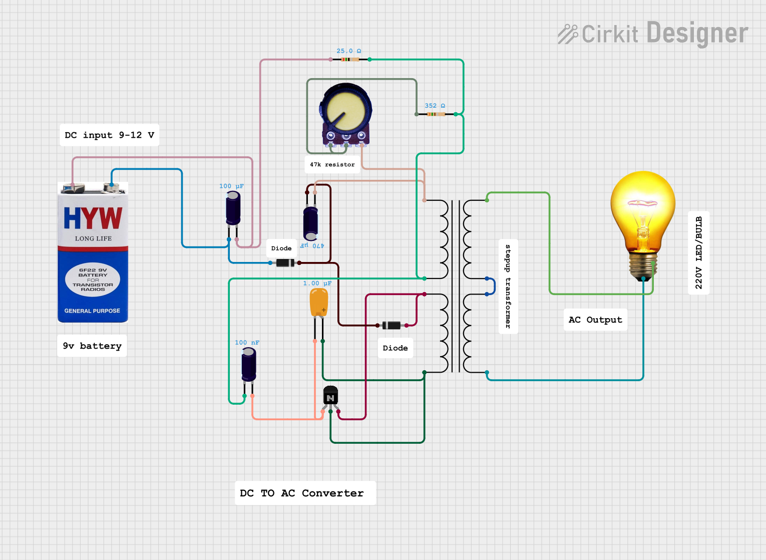
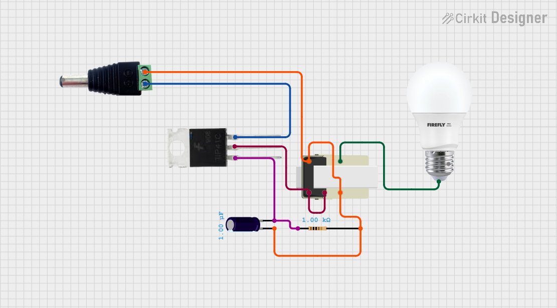
Example: Using a Transformer with an Arduino UNO
If you are using a transformer to power an Arduino UNO, you will need to step down the AC voltage and convert it to DC. Below is an example circuit and code:
Circuit Steps:
- Use a step-down transformer to reduce the AC voltage (e.g., 230V to 12V AC).
- Connect the transformer's secondary output to a bridge rectifier to convert AC to DC.
- Add a capacitor (e.g., 1000µF) across the rectifier output to smooth the DC voltage.
- Use a voltage regulator (e.g., 7805) to provide a stable 5V DC output for the Arduino UNO.
Arduino Code:
// Example code to read an analog sensor powered by a transformer
// Ensure the transformer output is properly regulated to 5V DC

const int sensorPin = A0;  // Analog pin connected to the sensor
int sensorValue = 0;       // Variable to store the sensor reading

void setup() {
  Serial.begin(9600);  // Initialize serial communication at 9600 baud
}

void loop() {
  sensorValue = analogRead(sensorPin);  // Read the sensor value
  Serial.print("Sensor Value: ");
  Serial.println(sensorValue);  // Print the sensor value to the Serial Monitor
  delay(1000);  // Wait for 1 second before the next reading
}
Troubleshooting and FAQs
Common Issues and Solutions
No Output Voltage:
- Cause: Incorrect wiring or no input voltage.
- Solution: Verify the connections on the primary and secondary sides. Ensure the input voltage is within the specified range.
Overheating Transformer:
- Cause: Overloading or insufficient ventilation.
- Solution: Reduce the load or provide better cooling. Ensure the transformer is not operating beyond its power rating.
Voltage Drop Under Load:
- Cause: Transformer is undersized for the application.
- Solution: Use a transformer with a higher power rating.
Humming Noise:
- Cause: Loose laminations or excessive magnetizing current.
- Solution: Tighten the core laminations or replace the transformer if the noise persists.
FAQs
Q: Can a transformer work with DC input?
A: No, transformers require AC input to function. DC input will not induce the necessary magnetic flux changes.Q: How do I calculate the power rating of a transformer?
A: Multiply the output voltage by the output current (P = V × I). Ensure the transformer's power rating exceeds this value.Q: Can I use a transformer to isolate circuits?
A: Yes, isolation transformers are specifically designed to electrically isolate the primary and secondary circuits for safety.Q: What happens if I reverse the primary and secondary sides?
A: The transformer may not function as intended, and the output voltage may exceed safe levels, potentially damaging connected devices.
By following this documentation, you can effectively use a transformer in your projects while ensuring safety and optimal performance.