Cirkit Designer Logo
Cirkit Designer
Your all-in-one circuit design IDE
Home / 
Component Documentation

How to Use Comment: Examples, Pinouts, and Specs

Image of Comment
Cirkit Designer LogoDesign with Comment in Cirkit Designer

Introduction

The Comment Electronic Component is a versatile and essential building block in various electronic circuits. It is commonly used in both educational and professional projects to provide feedback, explanations, or instructions within the code, schematics, or design documentation. Comments are crucial for maintaining code readability and understanding the functionality of electronic designs.

Common Applications and Use Cases

  • Educational Purposes: Teaching the principles of circuit design and coding.
  • Project Documentation: Providing clear instructions and explanations within schematics and code.
  • Code Maintenance: Assisting in future modifications and debugging by explaining the purpose and functionality of specific sections of code or circuit elements.

Technical Specifications

The Comment component does not have electrical characteristics like voltage or current ratings. Instead, its specifications pertain to its format and placement within documentation and code.

Pin Configuration and Descriptions

Since the Comment is not a physical electronic component, it does not have a pin configuration. However, in the context of code, it has a specific syntax that varies depending on the programming language.

Language Single-line Comment Multi-line Comment Start Multi-line Comment End
C/C++ // /* */
Python # ''' or """ ''' or """
HTML <!-- <!-- -->
Arduino // /* */

Usage Instructions

How to Use the Comment in a Circuit

As a non-physical component, the Comment is used within circuit diagrams and code to provide information. In circuit diagrams, comments can be added as text labels next to components or along signal lines. In code, comments are added by using the syntax specific to the programming language being used.

Important Considerations and Best Practices

  • Clarity: Comments should be clear and concise, providing valuable information without being overly verbose.
  • Relevance: Ensure that comments are relevant to the code or circuit element they are describing.
  • Maintenance: Keep comments updated as changes are made to the code or circuit design to prevent confusion.
  • Avoid Overuse: Too many comments can clutter the code or schematic, making it harder to follow.

Troubleshooting and FAQs

Common Issues Users Might Face

  • Outdated Comments: Comments that are not updated alongside code changes can lead to confusion.
  • Misleading Comments: Incorrect comments can misguide users and lead to improper use of the code or circuit.

Solutions and Tips for Troubleshooting

  • Regularly review and update comments to ensure they match the current state of the code or circuit.
  • If a piece of code or part of a circuit is not behaving as expected, check the comments to see if they provide insight into the intended functionality.

Example Code for Arduino UNO

Below is an example of how to use comments in an Arduino sketch:

// Define the LED pin
const int ledPin = 13;

void setup() {
  // Set the LED pin as an output
  pinMode(ledPin, OUTPUT);
}

void loop() {
  // Turn the LED on
  digitalWrite(ledPin, HIGH);
  // Wait for one second
  delay(1000);
  // Turn the LED off
  digitalWrite(ledPin, LOW);
  // Wait for one second
  delay(1000);
}

In this example, single-line comments are used to describe each line of code. This helps users understand the purpose of each command within the Arduino sketch.

Explore Projects Built with Comment
Use Cirkit Designer to design, explore, and prototype these projects online. Some projects support real-time simulation. Click "Open Project" to start designing instantly!
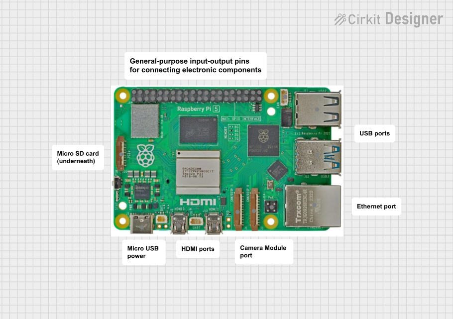
Raspberry Pi 5-Based Project with Custom Comments
Image of Raspberry Pi 5: A project utilizing Comment in a practical application
The circuit consists of a Raspberry Pi 5 with no additional electrical connections or code, suggesting it is either a placeholder for future development or a standalone component without any external interfacing in this configuration.
Cirkit Designer LogoOpen Project in Cirkit Designer
Arduino Mega-Controlled Robotic Vehicle with RF Communication and Sensor Integration
Image of Copy of Copy of Beach-Bot: A project utilizing Comment in a practical application
This circuit is designed for advanced motion control and environmental sensing, featuring motor control with feedback, distance measurement, and wireless communication. It is powered by renewable energy sources, making it suitable for autonomous, remote, or outdoor applications. The lack of embedded code indicates that the control logic for the system's operation is not yet implemented.
Cirkit Designer LogoOpen Project in Cirkit Designer
Arduino-Controlled Robotic Vehicle with RF Communication and Ultrasonic Sensing
Image of CC-Bot: A project utilizing Comment in a practical application
This circuit is designed for a robotic or automated system with motor control, power management, and sensory data collection. It features microcontroller-based control with Arduino UNO and Nano, motor drivers for actuation, and a mix of ultrasonic and LIDAR sensors for environmental sensing. Additionally, it includes RF communication and image capture capabilities, with power supplied by a solar panel and managed by a charge controller and BMS.
Cirkit Designer LogoOpen Project in Cirkit Designer
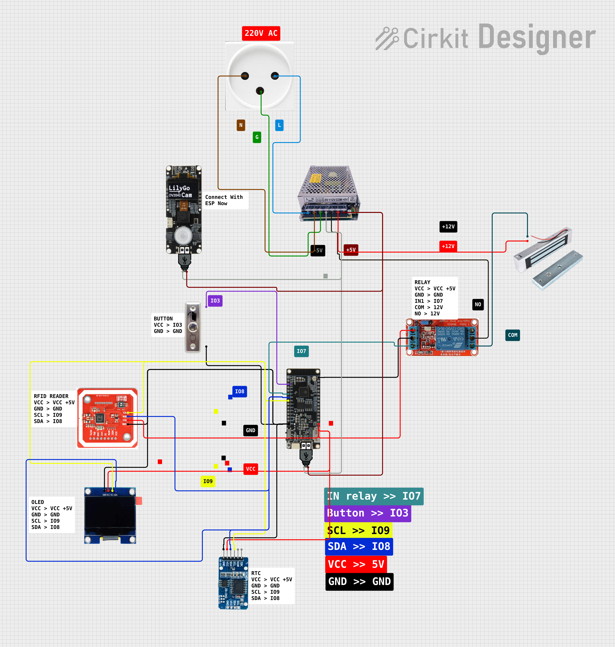
NFC-Enabled Access Control System with Real-Time Clock and OLED Display
Image of doorlock: A project utilizing Comment in a practical application
This circuit is designed as an access control system with time-tracking capabilities. It uses an NFC/RFID reader for authentication, a real-time clock for time-stamping events, and an OLED display for user interface, all controlled by a T8_S3 microcontroller. A relay module actuates a magnetic lock, and a button switch provides additional user input, with a switching power supply delivering the necessary voltages.
Cirkit Designer LogoOpen Project in Cirkit Designer

Explore Projects Built with Comment

Use Cirkit Designer to design, explore, and prototype these projects online. Some projects support real-time simulation. Click "Open Project" to start designing instantly!
Image of Raspberry Pi 5: A project utilizing Comment in a practical application
Raspberry Pi 5-Based Project with Custom Comments
The circuit consists of a Raspberry Pi 5 with no additional electrical connections or code, suggesting it is either a placeholder for future development or a standalone component without any external interfacing in this configuration.
Cirkit Designer LogoOpen Project in Cirkit Designer
Image of Copy of Copy of Beach-Bot: A project utilizing Comment in a practical application
Arduino Mega-Controlled Robotic Vehicle with RF Communication and Sensor Integration
This circuit is designed for advanced motion control and environmental sensing, featuring motor control with feedback, distance measurement, and wireless communication. It is powered by renewable energy sources, making it suitable for autonomous, remote, or outdoor applications. The lack of embedded code indicates that the control logic for the system's operation is not yet implemented.
Cirkit Designer LogoOpen Project in Cirkit Designer
Image of CC-Bot: A project utilizing Comment in a practical application
Arduino-Controlled Robotic Vehicle with RF Communication and Ultrasonic Sensing
This circuit is designed for a robotic or automated system with motor control, power management, and sensory data collection. It features microcontroller-based control with Arduino UNO and Nano, motor drivers for actuation, and a mix of ultrasonic and LIDAR sensors for environmental sensing. Additionally, it includes RF communication and image capture capabilities, with power supplied by a solar panel and managed by a charge controller and BMS.
Cirkit Designer LogoOpen Project in Cirkit Designer
Image of doorlock: A project utilizing Comment in a practical application
NFC-Enabled Access Control System with Real-Time Clock and OLED Display
This circuit is designed as an access control system with time-tracking capabilities. It uses an NFC/RFID reader for authentication, a real-time clock for time-stamping events, and an OLED display for user interface, all controlled by a T8_S3 microcontroller. A relay module actuates a magnetic lock, and a button switch provides additional user input, with a switching power supply delivering the necessary voltages.
Cirkit Designer LogoOpen Project in Cirkit Designer