How to Use 7-Segment Panel Celsius Thermometer: Examples, Pinouts, and Specs
Introduction
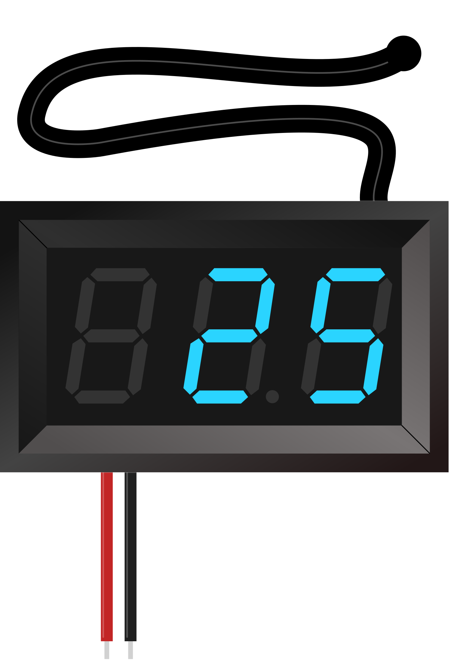
The 7-Segment Panel Celsius Thermometer is an electronic device designed to measure and display temperature readings in Celsius. It consists of a temperature sensor and a 7-segment LED display that visually represents the temperature value. This component is commonly used in a variety of applications, including environmental monitoring, climate control systems, hobbyist projects, and educational tools.
Explore Projects Built with 7-Segment Panel Celsius Thermometer
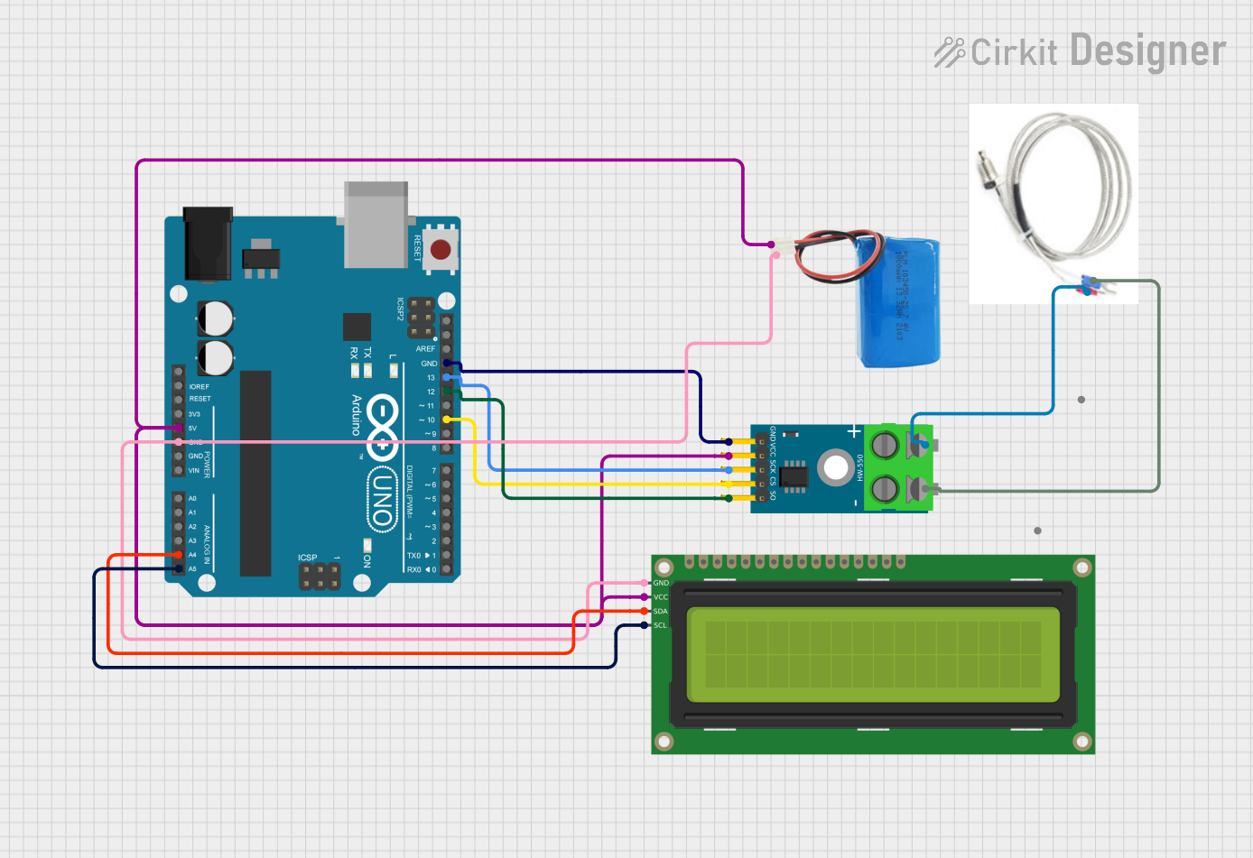

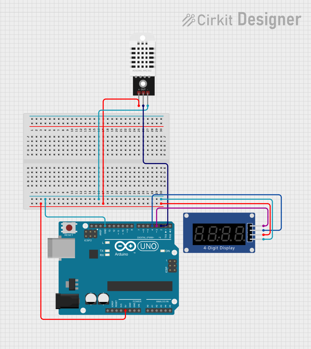
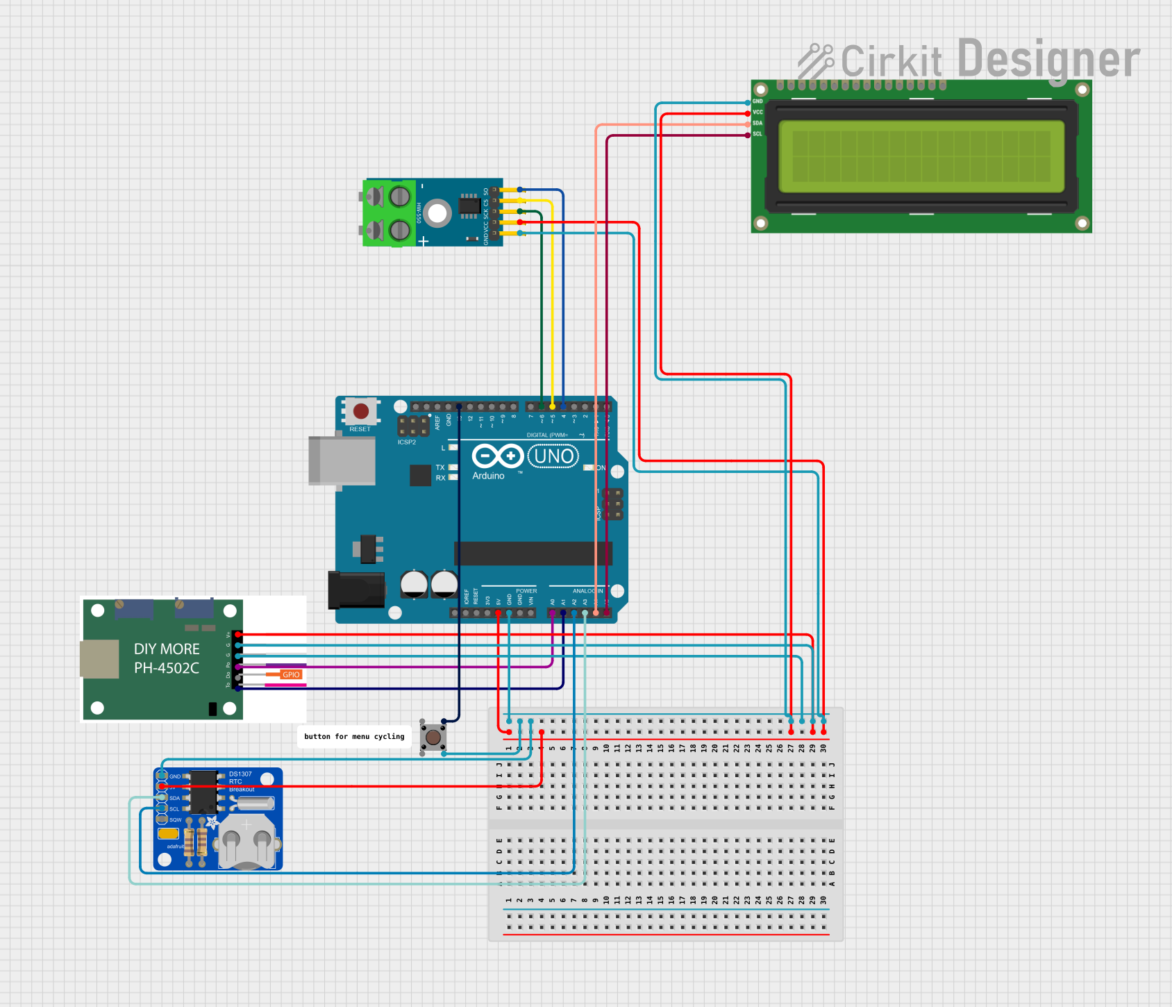
Explore Projects Built with 7-Segment Panel Celsius Thermometer
Common Applications and Use Cases
- Home and office temperature monitoring
- HVAC system feedback
- Laboratory experiments
- Educational demonstrations
- DIY electronics projects
Technical Specifications
Key Technical Details
- Temperature Range: -20°C to 70°C
- Accuracy: ±1°C
- Display Type: 7-segment LED
- Operating Voltage: 5V DC
- Current Consumption: 20mA typical
Pin Configuration and Descriptions
| Pin Number | Description | Notes |
|---|---|---|
| 1 | VCC | Connect to 5V power supply |
| 2 | Ground (GND) | Connect to system ground |
| 3 | Signal Out | Outputs temperature data signal |
| 4 | Decimal Point Control | Controls the decimal point LED |
Usage Instructions
How to Use the Component in a Circuit
- Power Connections: Connect the VCC pin to a 5V power supply and the GND pin to the common ground in your circuit.
- Signal Reading: Connect the Signal Out pin to a microcontroller's digital or analog input pin, depending on the output signal type.
- Decimal Point: Optionally, connect the Decimal Point Control pin to a digital output on your microcontroller if you wish to control the decimal point LED.
Important Considerations and Best Practices
- Ensure that the power supply does not exceed the recommended 5V to avoid damaging the component.
- Avoid placing the thermometer near heat-generating components to ensure accurate readings.
- Use a pull-up or pull-down resistor on the Signal Out pin if required by your microcontroller's input configuration.
Example Arduino UNO Code
// Define the pin connected to the Signal Out of the thermometer
const int thermometerPin = A0;

void setup() {
  // Initialize the Serial Monitor to display the temperature
  Serial.begin(9600);
}

void loop() {
  // Read the temperature value from the thermometer
  int sensorValue = analogRead(thermometerPin);
  // Convert the sensor value to temperature in Celsius
  float temperature = sensorValue * (5.0 / 1023.0) * 100.0;

  // Display the temperature on the Serial Monitor
  Serial.print("Temperature: ");
  Serial.print(temperature);
  Serial.println(" C");

  // Wait for a second before reading the temperature again
  delay(1000);
}
Troubleshooting and FAQs
Common Issues Users Might Face
- Inaccurate Temperature Readings: Ensure the thermometer is not placed near heat sources and that the power supply is stable.
- No Display Output: Check the connections to the VCC and GND pins, and ensure the Signal Out pin is correctly connected to the microcontroller.
- Dim or Flickering Display: Verify that the current consumption does not exceed the power supply capabilities and that all connections are secure.
Solutions and Tips for Troubleshooting
- Calibration: If possible, calibrate the thermometer using a known temperature source to ensure accuracy.
- Power Supply: Use a regulated power supply to prevent voltage fluctuations that could affect the readings.
- Connection Check: Revisit all connections, especially the Signal Out pin, to ensure they are secure and correct.
FAQs
Q: Can the thermometer be used outdoors? A: Yes, but it should be protected from direct sunlight, moisture, and extreme temperatures outside its operating range.
Q: How can I adjust the decimal point? A: The Decimal Point Control pin can be connected to a digital output on your microcontroller. You can then control it by setting the pin HIGH or LOW as needed.
Q: What is the refresh rate of the display? A: The refresh rate depends on the specific model of the thermometer. Check the datasheet for your particular component for this detail.
Q: Can I use this thermometer with a 3.3V system? A: The thermometer is designed for a 5V supply. Using it with a 3.3V system may result in dimmer display or incorrect readings. Check if a 3.3V compatible version is available.