How to Use RTC DS1302: Examples, Pinouts, and Specs
Introduction
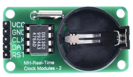
The DS1302 is a real-time clock (RTC) module designed to keep track of the current time and date, including seconds, minutes, hours, day, date, month, and year. It features a serial interface for communication with microcontrollers and includes a battery backup, allowing it to maintain accurate timekeeping even during power outages. The DS1302 is widely used in applications requiring precise timekeeping, such as data loggers, alarm systems, and embedded systems.
Explore Projects Built with RTC DS1302

Explore Projects Built with RTC DS1302
Common Applications:
- Digital clocks and timers
- Data logging systems
- Alarm systems
- Home automation
- Time-stamping in embedded systems
Technical Specifications
The DS1302 is a low-power RTC with the following key specifications:
| Parameter | Value |
|---|---|
| Operating Voltage | 2.0V to 5.5V |
| Backup Battery Voltage | 2.0V to 3.5V |
| Operating Temperature | -40°C to +85°C |
| Timekeeping Accuracy | ±2 minutes per month (at 25°C) |
| Communication Interface | Serial (3-wire) |
| Maximum Clock Frequency | 2 MHz |
| Current Consumption | < 300 nA (with battery backup) |
Pin Configuration and Descriptions
The DS1302 has an 8-pin configuration. Below is the pinout and description:
| Pin | Name | Description |
|---|---|---|
| 1 | VCC1 | Primary power supply (2.0V to 5.5V). |
| 2 | X1 | Oscillator input. Connect to a 32.768 kHz crystal. |
| 3 | X2 | Oscillator output. Connect to a 32.768 kHz crystal. |
| 4 | GND | Ground. |
| 5 | RST | Reset pin. Used to enable communication with the microcontroller. |
| 6 | I/O | Serial data input/output. |
| 7 | SCLK | Serial clock input. |
| 8 | VCC2 | Backup battery input (2.0V to 3.5V). |
Usage Instructions
How to Use the DS1302 in a Circuit
- Power Supply: Connect the VCC1 pin to the primary power source (e.g., 5V) and the GND pin to ground. For battery backup, connect a 3V coin cell battery to the VCC2 pin.
- Crystal Oscillator: Attach a 32.768 kHz crystal between the X1 and X2 pins. No external capacitors are required.
- Microcontroller Interface: Connect the RST, I/O, and SCLK pins to the corresponding GPIO pins on your microcontroller.
- Pull-Up Resistor: Use a pull-up resistor (typically 10kΩ) on the I/O line to ensure proper communication.
Important Considerations
- Ensure the backup battery is properly connected to maintain timekeeping during power outages.
- Avoid using long wires for the crystal oscillator connections to minimize noise and ensure accuracy.
- The DS1302 operates in 24-hour or 12-hour mode. Configure the mode as needed in your code.
Example Code for Arduino UNO
Below is an example of how to interface the DS1302 with an Arduino UNO to read and set the time:
#include <DS1302.h> // Include the DS1302 library

// Define the DS1302 pins connected to the Arduino
#define RST_PIN 7   // Reset pin
#define IO_PIN 6    // Data I/O pin
#define SCLK_PIN 5  // Serial clock pin

// Create an instance of the DS1302 class
DS1302 rtc(RST_PIN, IO_PIN, SCLK_PIN);

void setup() {
  Serial.begin(9600); // Initialize serial communication

  // Set the time and date (Year, Month, Day, Hour, Minute, Second)
  rtc.setTime(2023, 10, 15, 14, 30, 0); // Example: 15th Oct 2023, 14:30:00

  Serial.println("DS1302 RTC Initialized");
}

void loop() {
  // Read the current time and date
  Time t = rtc.getTime();

  // Print the time and date to the Serial Monitor
  Serial.print("Date: ");
  Serial.print(t.date); // Print the day
  Serial.print("/");
  Serial.print(t.mon);  // Print the month
  Serial.print("/");
  Serial.print(t.year); // Print the year
  Serial.print(" Time: ");
  Serial.print(t.hour); // Print the hour
  Serial.print(":");
  Serial.print(t.min);  // Print the minute
  Serial.print(":");
  Serial.println(t.sec); // Print the second

  delay(1000); // Wait for 1 second before updating
}
Notes:
- Install the
DS1302library in the Arduino IDE before uploading the code. - Modify the
rtc.setTime()function to set the desired initial time and date.
Troubleshooting and FAQs
Common Issues
Incorrect Timekeeping:
- Ensure the crystal oscillator is properly connected to the X1 and X2 pins.
- Verify that the backup battery is functional and correctly installed.
No Communication with Microcontroller:
- Check the connections between the DS1302 and the microcontroller.
- Ensure the RST, I/O, and SCLK pins are correctly assigned in the code.
Time Resets After Power Loss:
- Confirm that the backup battery is connected to the VCC2 pin.
- Replace the battery if it is depleted.
FAQs
Q: Can the DS1302 handle leap years?
A: Yes, the DS1302 automatically adjusts for leap years up to the year 2100.
Q: What happens if the backup battery is removed?
A: The DS1302 will lose its timekeeping functionality during power loss and reset to its default state.
Q: Can I use the DS1302 with a 3.3V microcontroller?
A: Yes, the DS1302 operates within a voltage range of 2.0V to 5.5V, making it compatible with 3.3V systems.
Q: How accurate is the DS1302?
A: The DS1302 has an accuracy of ±2 minutes per month at 25°C. For higher accuracy, consider temperature-compensated RTCs.