How to Use Transformateur 240V/24V: Examples, Pinouts, and Specs
Introduction
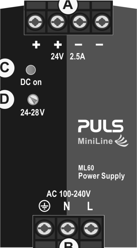
The PULS ML60 is a high-quality transformer designed to step down voltage from 240V AC to 24V AC. This component is widely used in low-voltage applications, providing a safe and reliable power source for various devices and systems. Its robust design ensures efficient energy conversion, making it ideal for industrial, commercial, and residential applications.
Explore Projects Built with Transformateur 240V/24V


Explore Projects Built with Transformateur 240V/24V
Common Applications and Use Cases
- Powering low-voltage devices such as sensors, relays, and actuators.
- Industrial control systems and automation equipment.
- LED lighting systems requiring 24V AC input.
- HVAC systems and other appliances with 24V control circuits.
- Educational and prototyping projects requiring a step-down transformer.
Technical Specifications
The following table outlines the key technical details of the PULS ML60 transformer:
| Parameter | Value |
|---|---|
| Input Voltage | 240V AC |
| Output Voltage | 24V AC |
| Power Rating | 60 VA |
| Frequency Range | 50/60 Hz |
| Efficiency | ≥ 90% |
| Operating Temperature | -20°C to +70°C |
| Insulation Class | Class B (130°C) |
| Mounting Type | DIN Rail or Panel Mount |
| Dimensions (L x W x H) | 90 mm x 70 mm x 60 mm |
| Weight | 0.8 kg |
Pin Configuration and Descriptions
The PULS ML60 transformer has the following terminal connections:
| Pin/Terminal | Description |
|---|---|
| L (Line) | 240V AC input (live wire) |
| N (Neutral) | 240V AC input (neutral wire) |
| PE (Protective Earth) | Ground connection for safety |
| 24V+ | 24V AC output (positive terminal) |
| 24V- | 24V AC output (negative terminal) |
Usage Instructions
How to Use the Component in a Circuit
- Mounting the Transformer: Secure the transformer to a DIN rail or panel using the provided mounting brackets. Ensure proper ventilation around the unit to prevent overheating.
- Wiring the Input:
- Connect the L (Line) terminal to the live wire of the 240V AC power source.
- Connect the N (Neutral) terminal to the neutral wire of the 240V AC power source.
- Connect the PE (Protective Earth) terminal to the ground for safety.
- Wiring the Output:
- Connect the 24V+ terminal to the positive input of the load or circuit.
- Connect the 24V- terminal to the negative input of the load or circuit.
- Power On: After verifying all connections, switch on the 240V AC power source. The transformer will step down the voltage to 24V AC, which can now be used to power your devices.
Important Considerations and Best Practices
- Overcurrent Protection: Use a fuse or circuit breaker on the input side to protect the transformer from overcurrent conditions.
- Load Compatibility: Ensure the connected load does not exceed the transformer's power rating of 60 VA.
- Grounding: Always connect the PE terminal to a proper ground to ensure safety and reduce electrical noise.
- Temperature Management: Avoid placing the transformer in enclosed or poorly ventilated spaces to prevent overheating.
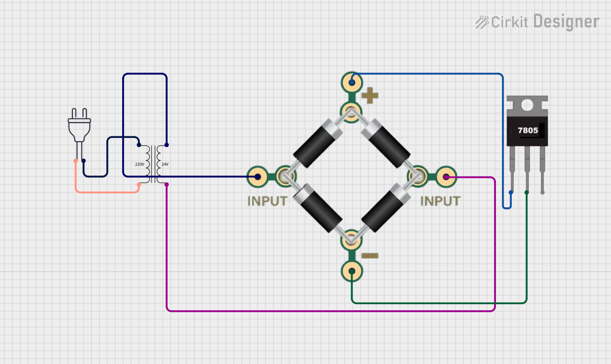
- AC Output: Note that the output is 24V AC, not DC. If DC is required, use a rectifier circuit after the transformer.
Example: Connecting to an Arduino UNO
If you need to power an Arduino UNO with this transformer, you must first convert the 24V AC output to 5V DC using a rectifier and voltage regulator circuit. Below is an example of Arduino code to read a sensor powered by the transformer:
// Example Arduino code to read a sensor powered by the transformer
// Ensure the 24V AC is rectified and regulated to 5V DC before connecting to Arduino

const int sensorPin = A0; // Analog pin connected to the sensor
int sensorValue = 0;      // Variable to store the sensor reading

void setup() {
  Serial.begin(9600); // Initialize serial communication at 9600 baud
  pinMode(sensorPin, INPUT); // Set the sensor pin as input
}

void loop() {
  sensorValue = analogRead(sensorPin); // Read the sensor value
  Serial.print("Sensor Value: ");
  Serial.println(sensorValue); // Print the sensor value to the Serial Monitor
  delay(1000); // Wait for 1 second before the next reading
}
Troubleshooting and FAQs
Common Issues Users Might Face
No Output Voltage:
- Cause: Incorrect wiring or loose connections.
- Solution: Double-check all input and output connections. Ensure the power source is active.
Overheating:
- Cause: Overloading the transformer or poor ventilation.
- Solution: Reduce the load to within the 60 VA rating. Improve ventilation around the transformer.
Humming Noise:
- Cause: Loose mounting or high inrush current.
- Solution: Securely mount the transformer and ensure the load is within specifications.
Output Voltage Fluctuations:
- Cause: Unstable input voltage or excessive load.
- Solution: Verify the input voltage stability and reduce the load if necessary.
Solutions and Tips for Troubleshooting
- Use a multimeter to measure the input and output voltages to identify any discrepancies.
- Ensure the transformer is not exposed to moisture or extreme temperatures.
- If the transformer fails to operate, inspect for visible damage or contact the manufacturer for support.
By following this documentation, you can safely and effectively use the PULS ML60 transformer in your projects and applications.