
How to Use DRV8833 Motor Driver: Examples, Pinouts, and Specs
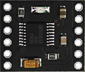
 Design with DRV8833 Motor Driver in Cirkit Designer
Introduction
The DRV8833 is a dual H-bridge motor driver designed for controlling two DC motors or a single stepper motor. It operates within a voltage range of 2.7V to 10.8V, making it suitable for low-voltage motor control applications. The DRV8833 includes advanced features such as adjustable current limiting, thermal shutdown, and overcurrent protection, ensuring reliable operation and protection for both the driver and the connected motors.
Explore Projects Built with DRV8833 Motor Driver
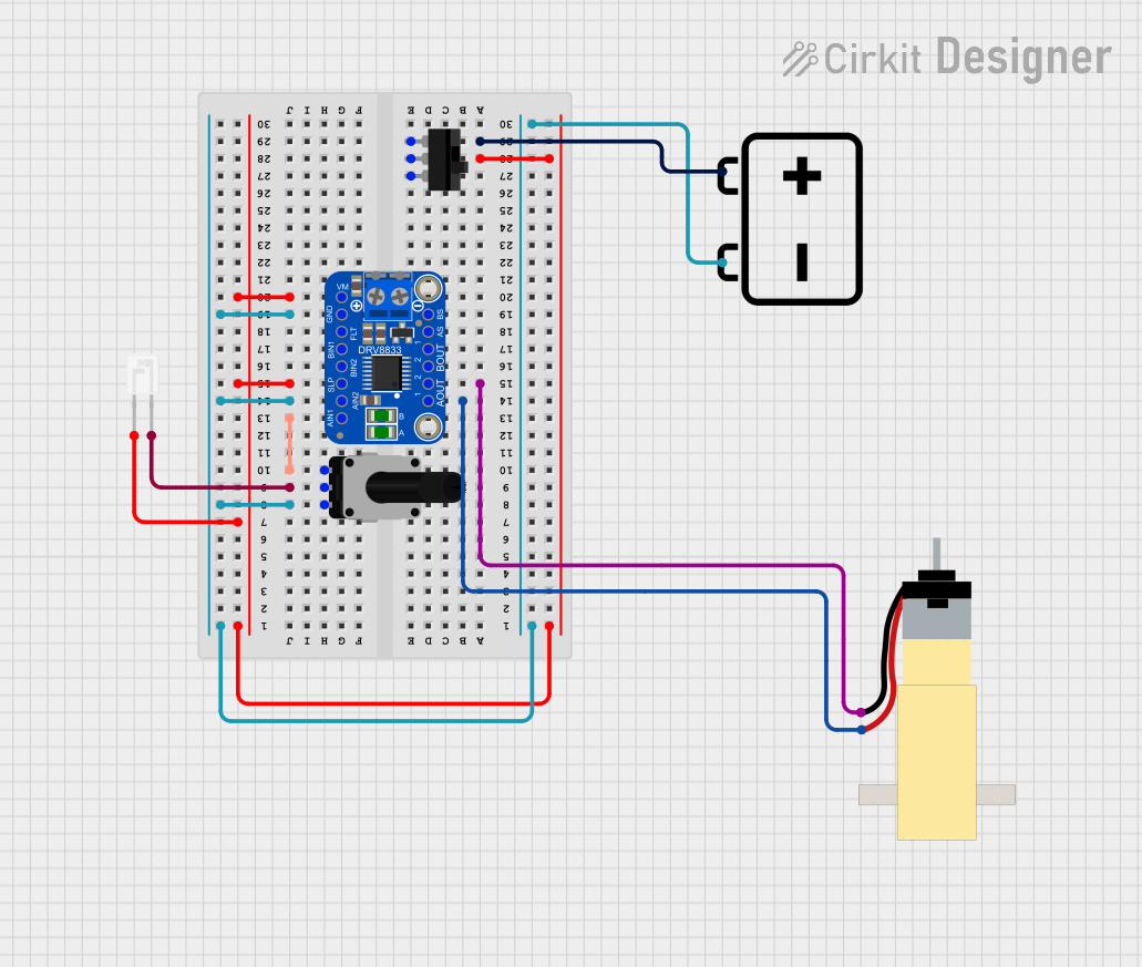 Open Project in Cirkit Designer
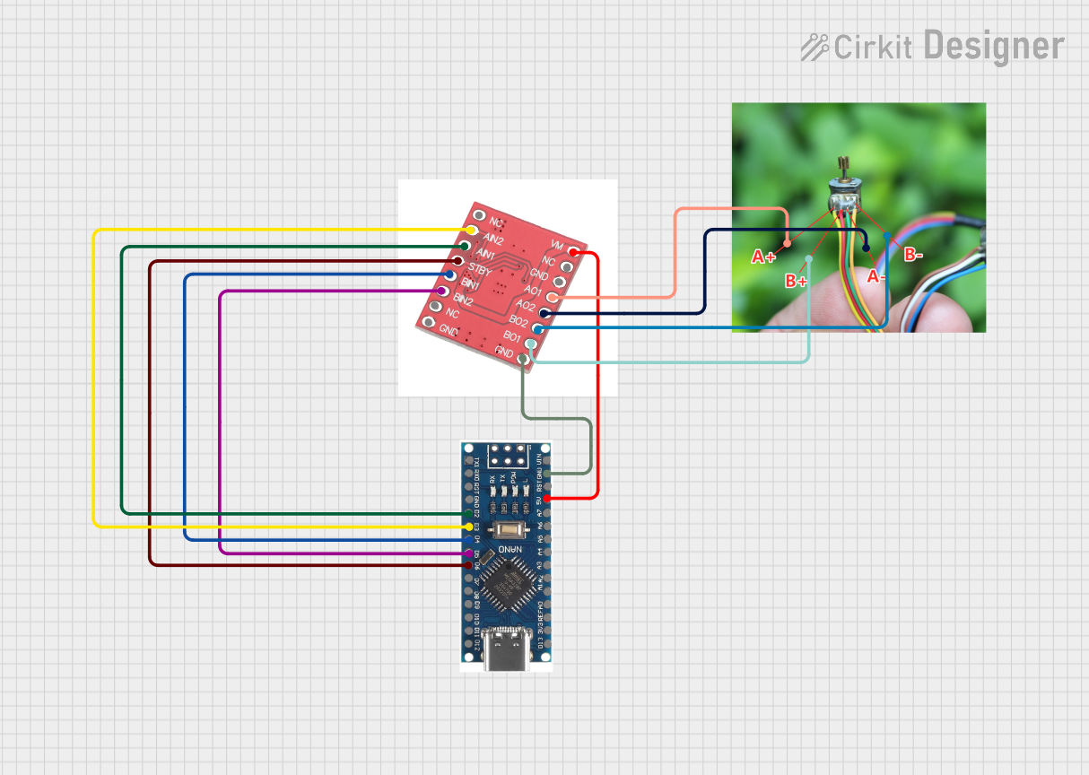 Open Project in Cirkit Designer
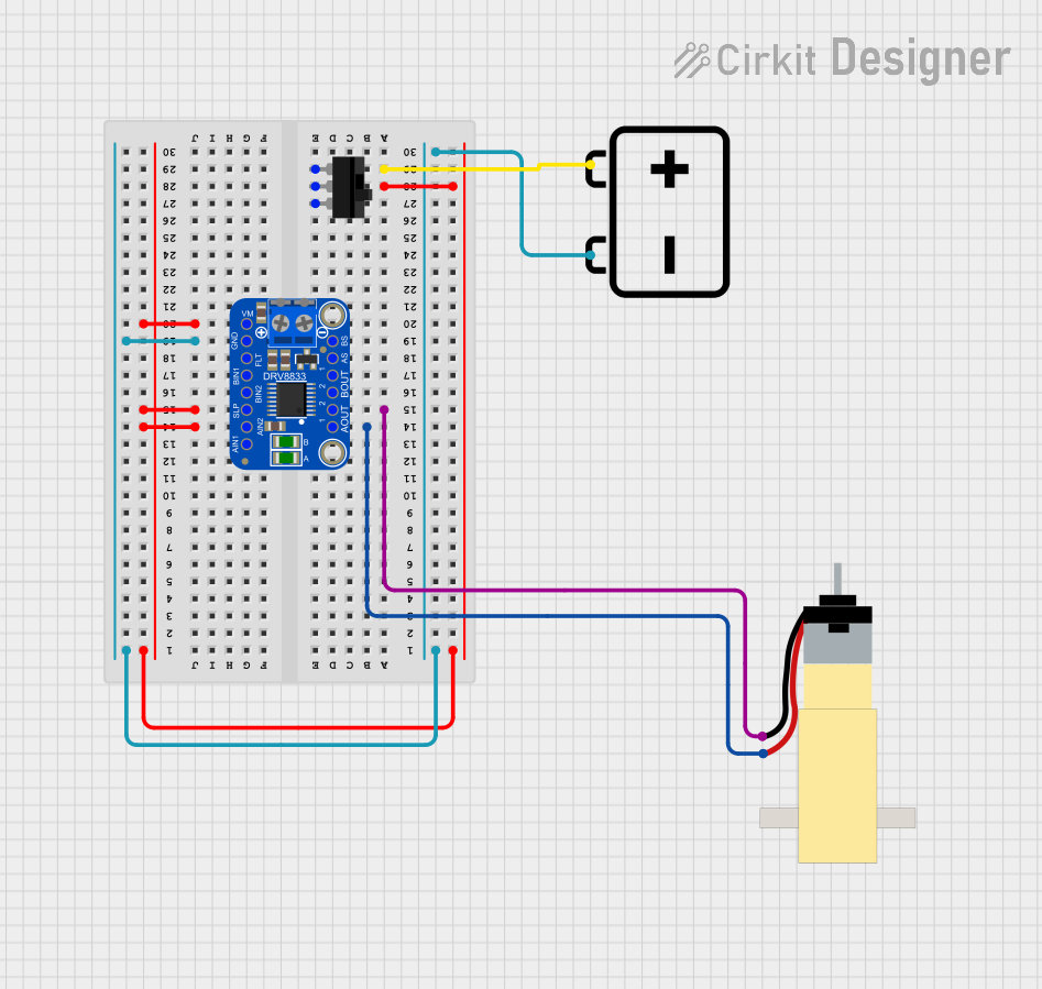 Open Project in Cirkit Designer
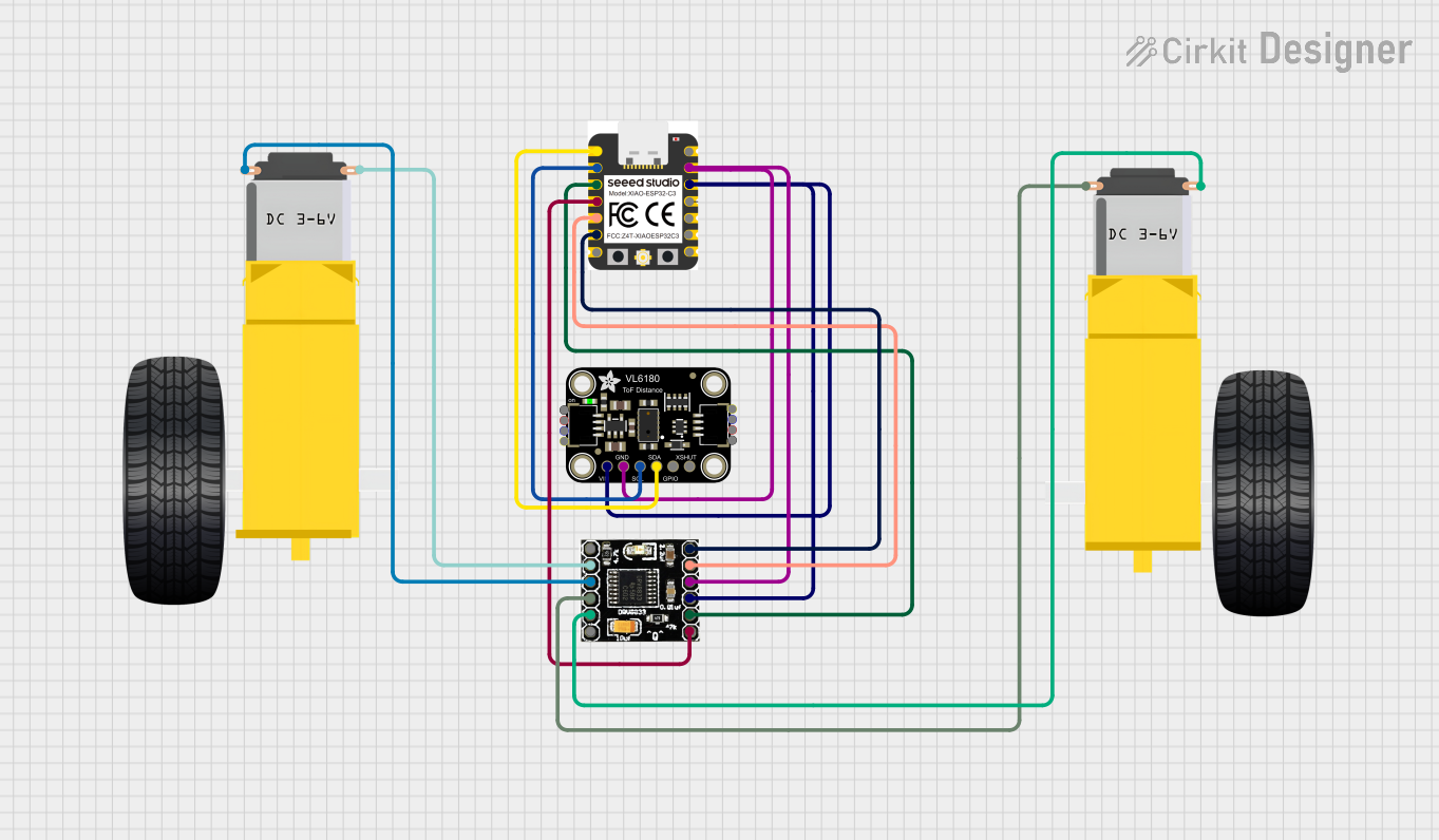 Open Project in Cirkit Designer
Explore Projects Built with DRV8833 Motor Driver
Open Project in Cirkit DesignerOpen Project in Cirkit DesignerOpen Project in Cirkit DesignerOpen Project in Cirkit DesignerCommon Applications and Use Cases
- Robotics: Driving small DC motors or stepper motors in robotic systems.
- Consumer Electronics: Motorized mechanisms in toys, cameras, and printers.
- DIY Projects: Controlling motors in Arduino or Raspberry Pi-based projects.
- Industrial Automation: Low-power motor control in automated systems.
Technical Specifications
Key Technical Details
- Operating Voltage Range: 2.7V to 10.8V
- Output Current (per channel): Up to 1.5A (peak), 1A (continuous)
- Control Interface: PWM or GPIO
- Protection Features: Overcurrent protection, thermal shutdown, undervoltage lockout
- Motor Types Supported: DC motors, stepper motors
- Package Type: HTSSOP (16-pin)
Pin Configuration and Descriptions
The DRV8833 comes in a 16-pin HTSSOP package. Below is the pin configuration:
| Pin Number | Pin Name | Description |
|---|---|---|
| 1 | AOUT1 | Output 1 for H-bridge A |
| 2 | AOUT2 | Output 2 for H-bridge A |
| 3 | VM | Motor power supply (2.7V to 10.8V) |
| 4 | GND | Ground connection |
| 5 | BOUT1 | Output 1 for H-bridge B |
| 6 | BOUT2 | Output 2 for H-bridge B |
| 7 | VCC | Logic power supply (typically 3.3V or 5V) |
| 8 | ENABLE | Enable pin for both H-bridges (active high) |
| 9 | AIN1 | Input 1 for H-bridge A (controls direction and speed with PWM) |
| 10 | AIN2 | Input 2 for H-bridge A (controls direction and speed with PWM) |
| 11 | BIN1 | Input 1 for H-bridge B (controls direction and speed with PWM) |
| 12 | BIN2 | Input 2 for H-bridge B (controls direction and speed with PWM) |
| 13 | NC | No connection |
| 14 | NC | No connection |
| 15 | FAULT | Fault indicator (active low, indicates overcurrent or thermal shutdown) |
| 16 | SLEEP | Sleep mode pin (active low, reduces power consumption when not in use) |
Usage Instructions
How to Use the DRV8833 in a Circuit
Power Supply:
- Connect the motor power supply (VM) to the VM pin. Ensure the voltage is within the range of 2.7V to 10.8V.
- Connect the logic power supply (VCC) to the VCC pin. Typically, this is 3.3V or 5V.
- Connect the GND pin to the ground of your circuit.
Motor Connections:
- For DC motors, connect the motor terminals to the AOUT1/AOUT2 pins (H-bridge A) or BOUT1/BOUT2 pins (H-bridge B).
- For stepper motors, connect the two coils to the AOUT1/AOUT2 and BOUT1/BOUT2 pins.
Control Signals:
- Use the AIN1/AIN2 and BIN1/BIN2 pins to control the direction and speed of the motors. Apply PWM signals to these pins for speed control.
- Set the ENABLE pin high to activate the H-bridges. Pull it low to disable the outputs.
Sleep Mode:
- Pull the SLEEP pin low to put the driver into low-power mode. Pull it high to enable normal operation.
Fault Handling:
- Monitor the FAULT pin for error conditions. If the pin goes low, check for overcurrent or thermal shutdown issues.
Important Considerations and Best Practices
- Current Limiting: Ensure the motor current does not exceed the maximum continuous current rating of 1A per channel to avoid damage.
- Heat Dissipation: Use proper heat sinking or cooling if operating near the maximum current or in high-temperature environments.
- Decoupling Capacitors: Place a decoupling capacitor (e.g., 100µF) close to the VM pin to stabilize the motor power supply.
- Logic Level Compatibility: Ensure the control signals (AIN1, AIN2, BIN1, BIN2) are compatible with the logic voltage (VCC).
Example: Using DRV8833 with Arduino UNO
Below is an example of controlling a single DC motor using the DRV8833 and Arduino UNO:
// Define motor control pins
const int AIN1 = 9;  // Connect to AIN1 pin of DRV8833
const int AIN2 = 10; // Connect to AIN2 pin of DRV8833
const int ENABLE = 8; // Connect to ENABLE pin of DRV8833

void setup() {
  // Set motor control pins as outputs
  pinMode(AIN1, OUTPUT);
  pinMode(AIN2, OUTPUT);
  pinMode(ENABLE, OUTPUT);

  // Enable the motor driver
  digitalWrite(ENABLE, HIGH);
}

void loop() {
  // Rotate motor forward
  digitalWrite(AIN1, HIGH);
  digitalWrite(AIN2, LOW);
  delay(2000); // Run motor for 2 seconds

  // Rotate motor backward
  digitalWrite(AIN1, LOW);
  digitalWrite(AIN2, HIGH);
  delay(2000); // Run motor for 2 seconds

  // Stop motor
  digitalWrite(AIN1, LOW);
  digitalWrite(AIN2, LOW);
  delay(2000); // Stop for 2 seconds
}
Troubleshooting and FAQs
Common Issues and Solutions
Motor Not Spinning:
Cause: ENABLE pin is not set high.
Solution: Ensure the ENABLE pin is connected to a HIGH signal.
Cause: Incorrect wiring of motor terminals.
Solution: Verify the motor connections to AOUT1/AOUT2 or BOUT1/BOUT2.
Overheating:
- Cause: Excessive current draw from the motor.
- Solution: Check the motor specifications and ensure the current is within the DRV8833's limits. Use current limiting if necessary.
FAULT Pin is Low:
- Cause: Overcurrent or thermal shutdown.
- Solution: Reduce the motor load or improve heat dissipation.
No Response to Control Signals:
- Cause: Logic voltage (VCC) is not supplied or incompatible.
- Solution: Ensure the VCC pin is connected to a 3.3V or 5V source and matches the control signal levels.
FAQs
Q: Can I use the DRV8833 to control a stepper motor?
A: Yes, the DRV8833 can control a bipolar stepper motor by driving its two coils using the two H-bridges.Q: What happens if the motor draws more than 1A continuously?
A: The DRV8833 may enter thermal shutdown or overcurrent protection mode to prevent damage.Q: Can I leave unused pins floating?
A: No, unused input pins (e.g., AIN1, AIN2) should be tied to a defined logic level (HIGH or LOW) to avoid unpredictable behavior.