How to Use FLYWOO GOKU GM10 Pro V3 GPS с компасом: Examples, Pinouts, and Specs
Introduction
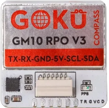
The FLYWOO GOKU GM10 Pro V3 GPS с компасом is a high-performance GPS module with an integrated compass, specifically designed for drones, UAVs, and other robotics applications. This module provides precise positioning and navigation capabilities, making it an essential component for autonomous systems and flight controllers. Its compact design and robust performance make it ideal for use in environments where accuracy and reliability are critical.
Explore Projects Built with FLYWOO GOKU GM10 Pro V3 GPS с компасом


Explore Projects Built with FLYWOO GOKU GM10 Pro V3 GPS с компасом
Common Applications and Use Cases
- GPS-based navigation for drones and UAVs
- Autonomous robotics and vehicles
- Return-to-home (RTH) functionality in flight controllers
- Position hold and waypoint navigation
- Geographic data logging and mapping
Technical Specifications
Below are the key technical details and pin configuration for the FLYWOO GOKU GM10 Pro V3 GPS с компасом:
Key Technical Details
| Parameter | Specification |
|---|---|
| GPS Chipset | Ublox M10 |
| Compass | QMC5883L |
| Positioning Accuracy | ±1.5 meters |
| Update Rate | Up to 10 Hz |
| Operating Voltage | 5V DC |
| Operating Current | 40 mA (typical) |
| Communication Interface | UART (GPS), I2C (Compass) |
| Dimensions | 18mm x 18mm x 6mm |
| Weight | 5 grams |
| Antenna | Integrated ceramic patch antenna |
| Mounting | M2 screw holes |
Pin Configuration and Descriptions
| Pin Number | Pin Name | Description |
|---|---|---|
| 1 | VCC | Power input (5V DC) |
| 2 | GND | Ground |
| 3 | RX | UART Receive (connect to TX of MCU) |
| 4 | TX | UART Transmit (connect to RX of MCU) |
| 5 | SDA | I2C Data line for compass communication |
| 6 | SCL | I2C Clock line for compass communication |
Usage Instructions
How to Use the Component in a Circuit
- Power Connection: Connect the
VCCpin to a 5V DC power source and theGNDpin to the ground of your circuit. - GPS Communication: Use the
RXandTXpins to establish UART communication with your microcontroller or flight controller. Ensure the baud rate is configured correctly (default: 9600 bps). - Compass Communication: Connect the
SDAandSCLpins to the I2C bus of your microcontroller. Pull-up resistors (typically 4.7kΩ) may be required on the I2C lines. - Mounting: Secure the module using the M2 screw holes. Ensure the GPS antenna faces upward for optimal satellite reception.
Important Considerations and Best Practices
- Placement: Install the module away from sources of electromagnetic interference (e.g., motors, ESCs, or power lines) to ensure accurate readings.
- Compass Calibration: Perform compass calibration before use to account for local magnetic field variations.
- Baud Rate Configuration: If needed, configure the GPS module's baud rate using Ublox's u-center software.
- Antenna Orientation: Ensure the ceramic patch antenna has a clear view of the sky for optimal satellite lock.
Example: Connecting to an Arduino UNO
Below is an example of how to connect and use the FLYWOO GOKU GM10 Pro V3 GPS с компасом with an Arduino UNO:
Wiring
| GPS Pin | Arduino Pin |
|---|---|
| VCC | 5V |
| GND | GND |
| RX | D3 |
| TX | D4 |
| SDA | A4 |
| SCL | A5 |
Code Example
#include <SoftwareSerial.h>
#include <Wire.h>
#include <Adafruit_Sensor.h>
#include <Adafruit_QMC5883L.h>

// Create a SoftwareSerial instance for GPS communication
SoftwareSerial gpsSerial(3, 4); // RX, TX

// Create an instance of the QMC5883L compass
Adafruit_QMC5883L compass;

void setup() {
  // Initialize serial communication
  Serial.begin(9600);
  gpsSerial.begin(9600);

  // Initialize the compass
  if (!compass.begin()) {
    Serial.println("Compass not detected. Check wiring!");
    while (1);
  }
  Serial.println("Compass initialized successfully.");
}

void loop() {
  // Read GPS data
  while (gpsSerial.available()) {
    char c = gpsSerial.read();
    Serial.print(c); // Print GPS data to the Serial Monitor
  }

  // Read compass data
  sensors_event_t event;
  compass.getEvent(&event);
  Serial.print("Heading: ");
  Serial.println(event.orientation.x); // Print compass heading
  delay(500);
}
Notes:
- Install the
Adafruit_SensorandAdafruit_QMC5883Llibraries in the Arduino IDE for compass functionality. - Ensure the GPS module has a clear view of the sky for satellite lock.
Troubleshooting and FAQs
Common Issues and Solutions
No GPS Lock:
- Ensure the module has a clear view of the sky.
- Check the power supply voltage and current.
- Wait for a few minutes, as the first satellite lock may take longer.
Compass Not Detected:
- Verify the I2C connections (SDA and SCL).
- Check for proper pull-up resistors on the I2C lines.
- Ensure the compass is initialized correctly in the code.
Incorrect Compass Readings:
- Perform a compass calibration.
- Avoid placing the module near magnetic or metallic objects.
No Data from GPS:
- Verify the UART connections (RX and TX).
- Check the baud rate configuration in the code.
FAQs
Q: Can this module be used with flight controllers like Betaflight?
A: Yes, the FLYWOO GOKU GM10 Pro V3 GPS с компасом is compatible with most flight controllers that support GPS and compass functionality, including Betaflight and INAV.
Q: What is the default I2C address of the compass?
A: The default I2C address of the QMC5883L compass is 0x0D.
Q: How many satellites are required for a 3D fix?
A: A minimum of 4 satellites is required for a 3D GPS fix.
Q: Can the module operate at 3.3V?
A: No, the module requires a 5V power supply for proper operation.