
How to Use Terminal Adapter for ESP32 30 Pin: Examples, Pinouts, and Specs
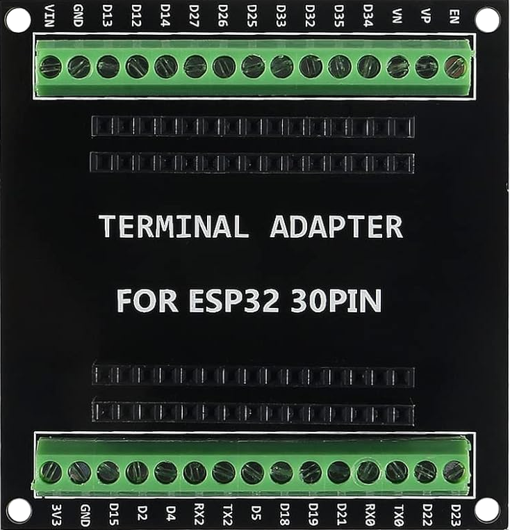
 Design with Terminal Adapter for ESP32 30 Pin in Cirkit Designer
Introduction
The Terminal Adapter for ESP32 30 Pin is a connector board designed to simplify prototyping and development with the ESP32 microcontroller. It provides easy access to all 30 pins of the ESP32, allowing for quick and reliable connections to external components such as sensors, actuators, and other peripherals. This adapter is particularly useful for breadboard-based projects, as it eliminates the need for complex wiring and ensures a stable connection.
Explore Projects Built with Terminal Adapter for ESP32 30 Pin
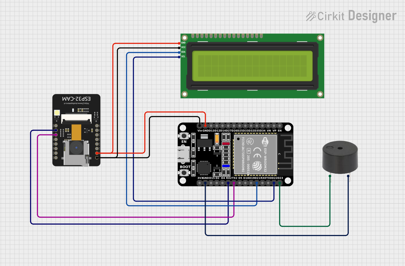
 Open Project in Cirkit Designer
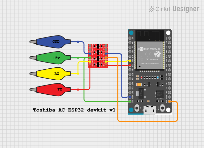
 Open Project in Cirkit Designer
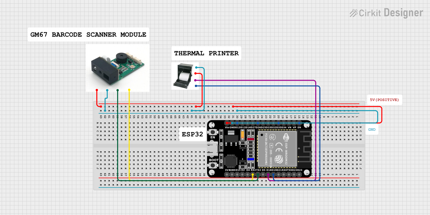
 Open Project in Cirkit Designer
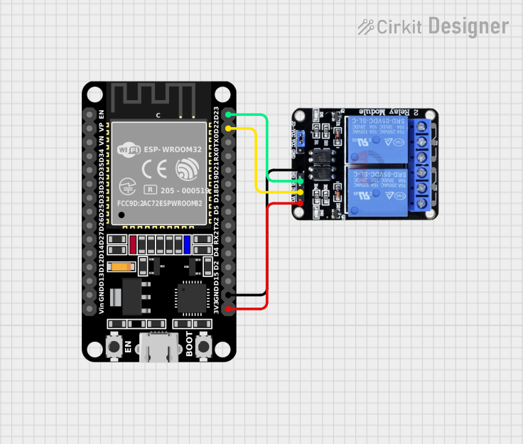
 Open Project in Cirkit Designer
Explore Projects Built with Terminal Adapter for ESP32 30 Pin

 Open Project in Cirkit Designer
 Open Project in Cirkit Designer
 Open Project in Cirkit Designer
 Open Project in Cirkit Designer
Common Applications and Use Cases
- Prototyping IoT devices with the ESP32 microcontroller
- Connecting sensors, actuators, and other peripherals to the ESP32
- Simplifying breadboard-based circuit designs
- Educational projects and rapid prototyping
Technical Specifications
The Terminal Adapter for ESP32 30 Pin is designed to work seamlessly with the ESP32 microcontroller. Below are its key technical details:
Key Specifications
- Compatibility: ESP32 30-pin development boards
- Dimensions: Matches the ESP32 30-pin form factor
- Pin Access: Breaks out all 30 pins of the ESP32
- Connector Type: Screw terminals for secure wiring
- Voltage Range: Supports the ESP32's operating voltage (3.3V logic)
- Material: High-quality PCB with durable screw terminals
Pin Configuration and Descriptions
The terminal adapter provides access to all 30 pins of the ESP32. Below is a table describing the pin layout:
| Pin Number | ESP32 Pin Name | Description |
|---|---|---|
| 1 | VIN | Input voltage (5V) |
| 2 | GND | Ground |
| 3 | IO23 | GPIO23, general-purpose I/O |
| 4 | IO22 | GPIO22, general-purpose I/O |
| 5 | IO21 | GPIO21, I2C SDA |
| 6 | IO19 | GPIO19, general-purpose I/O |
| 7 | IO18 | GPIO18, SPI SCK |
| 8 | IO17 | GPIO17, general-purpose I/O |
| 9 | IO16 | GPIO16, general-purpose I/O |
| 10 | IO15 | GPIO15, general-purpose I/O |
| 11 | IO14 | GPIO14, SPI SCK |
| 12 | IO13 | GPIO13, SPI MOSI |
| 13 | IO12 | GPIO12, SPI MISO |
| 14 | IO11 | GPIO11, general-purpose I/O |
| 15 | IO10 | GPIO10, general-purpose I/O |
| 16 | IO9 | GPIO9, general-purpose I/O |
| 17 | IO8 | GPIO8, general-purpose I/O |
| 18 | IO7 | GPIO7, general-purpose I/O |
| 19 | IO6 | GPIO6, general-purpose I/O |
| 20 | IO5 | GPIO5, general-purpose I/O |
| 21 | IO4 | GPIO4, general-purpose I/O |
| 22 | IO3 | GPIO3, UART RX |
| 23 | IO2 | GPIO2, general-purpose I/O |
| 24 | IO1 | GPIO1, UART TX |
| 25 | IO0 | GPIO0, general-purpose I/O |
| 26 | EN | Enable pin |
| 27 | 3V3 | 3.3V output |
| 28 | GND | Ground |
| 29 | IO34 | GPIO34, input-only |
| 30 | IO35 | GPIO35, input-only |
Usage Instructions
How to Use the Terminal Adapter
- Attach the ESP32: Insert the ESP32 development board into the terminal adapter, ensuring proper alignment of the pins.
- Connect Wires: Use the screw terminals to securely connect wires to the desired pins. Tighten the screws to ensure a stable connection.
- Power the ESP32: Provide power to the ESP32 through the VIN pin (5V) or the 3.3V pin, depending on your setup.
- Connect Peripherals: Attach sensors, actuators, or other components to the appropriate GPIO pins using the terminal adapter.
Important Considerations and Best Practices
- Voltage Levels: Ensure that all connected peripherals operate at 3.3V logic levels to avoid damaging the ESP32.
- Pin Usage: Refer to the ESP32 datasheet to understand the functionality of each pin (e.g., ADC, PWM, UART).
- Secure Connections: Double-check that all screw terminals are tightened to prevent loose connections.
- Breadboard Compatibility: The terminal adapter is designed for breadboard use, but ensure that the breadboard is stable and free of shorts.
Example: Connecting an LED to GPIO23
Below is an example of how to connect an LED to GPIO23 using the terminal adapter and control it with an Arduino sketch:
Circuit Setup
- Connect the positive leg of the LED to GPIO23 via the terminal adapter.
- Connect the negative leg of the LED to a 330-ohm resistor, and then to GND.
Arduino Code
// Define the GPIO pin for the LED
const int ledPin = 23;

void setup() {
  // Set the LED pin as an output
  pinMode(ledPin, OUTPUT);
}

void loop() {
  // Turn the LED on
  digitalWrite(ledPin, HIGH);
  delay(1000); // Wait for 1 second

  // Turn the LED off
  digitalWrite(ledPin, LOW);
  delay(1000); // Wait for 1 second
}
Troubleshooting and FAQs
Common Issues and Solutions
ESP32 Not Powering On
- Cause: Incorrect power supply or loose connections.
- Solution: Ensure the VIN pin is supplied with 5V or the 3.3V pin is properly powered.
Peripheral Not Responding
- Cause: Incorrect wiring or pin configuration.
- Solution: Double-check the wiring and ensure the correct GPIO pin is used in the code.
Loose Connections
- Cause: Screw terminals not tightened properly.
- Solution: Tighten all screw terminals securely to ensure stable connections.
Breadboard Instability
- Cause: Poor-quality breadboard or improper placement.
- Solution: Use a high-quality breadboard and ensure the terminal adapter is firmly seated.
FAQs
Q: Can I use 5V peripherals with this terminal adapter?
A: The ESP32 operates at 3.3V logic levels. If you need to use 5V peripherals, a level shifter is required.
Q: Is the terminal adapter compatible with all ESP32 boards?
A: The terminal adapter is specifically designed for ESP32 boards with a 30-pin layout. Ensure your ESP32 matches this form factor.
Q: Can I use this adapter for permanent installations?
A: While the terminal adapter is ideal for prototyping, it is not recommended for permanent installations due to its breadboard-oriented design.