Cirkit Designer Logo
Cirkit Designer
Your all-in-one circuit design IDE
Home / 
Component Documentation

How to Use HW-550 THERMOCOUPLE: Examples, Pinouts, and Specs

Image of HW-550 THERMOCOUPLE
Cirkit Designer LogoDesign with HW-550 THERMOCOUPLE in Cirkit Designer

Introduction

The HW-550 Thermocouple is a temperature sensor designed to measure temperature by utilizing the Seebeck effect, where a voltage is generated due to the temperature difference between two junctions of dissimilar metals. This component is widely used in industrial, scientific, and engineering applications for accurate temperature monitoring and control. Its robust design and high-temperature range make it suitable for environments such as furnaces, engines, and manufacturing processes.

Explore Projects Built with HW-550 THERMOCOUPLE

Use Cirkit Designer to design, explore, and prototype these projects online. Some projects support real-time simulation. Click "Open Project" to start designing instantly!
Arduino UNO Based Temperature Monitoring System with MAX6675 and RTC
Image of Labby Mark1: A project utilizing HW-550 THERMOCOUPLE in a practical application
This circuit features an Arduino UNO microcontroller interfaced with a MAX6675 thermocouple module, a ph4502c sensor module, an Adafruit DS1307 real-time clock (RTC) module, and an I2C LCD 16x2 display. The Arduino reads temperature data from the MAX6675, pH and temperature from the ph4502c, and time from the RTC, displaying this information on the LCD. A pushbutton is connected to the Arduino for potential user input, and all modules are powered by the Arduino's 5V output.
Cirkit Designer LogoOpen Project in Cirkit Designer
Arduino UNO Based Temperature Monitoring System with OLED Display
Image of schematic: A project utilizing HW-550 THERMOCOUPLE in a practical application
This circuit features an Arduino UNO microcontroller interfaced with a MAX6675 thermocouple module and a 0.96" OLED display. The Arduino reads temperature data from the MAX6675 module, which is connected to a K-type thermocouple, and communicates with the OLED display via I2C to show the temperature readings. Additionally, there are unused components such as a flange, rotary pump, pressure gauge, hose, and a variable transformer connected to a quartz crystal, which do not seem to be integrated into the main functionality of the circuit based on the provided net list and code.
Cirkit Designer LogoOpen Project in Cirkit Designer
Arduino UNO Thermocouple Temperature Monitor with I2C LCD Display
Image of saleh: A project utilizing HW-550 THERMOCOUPLE in a practical application
This circuit is a temperature measurement system using an Arduino UNO, a MAX6675 thermocouple module, and a 16x2 I2C LCD. The Arduino reads temperature data from the thermocouple via the MAX6675 module and displays the temperature in both Celsius and Fahrenheit on the LCD.
Cirkit Designer LogoOpen Project in Cirkit Designer
ESP8266 NodeMCU with MAX6675 Thermocouple Interface for Temperature Monitoring
Image of UAS Metrin: A project utilizing HW-550 THERMOCOUPLE in a practical application
This circuit is designed to measure temperature using a Type K thermocouple connected to a MAX6675 module, which digitizes the temperature reading. The MAX6675 module interfaces with an ESP8266 NodeMCU microcontroller over a SPI connection, using D5 (SCK), D6 (SO), and D8 (CS) for clock, data output, and chip select, respectively. The ESP8266 is responsible for processing the temperature data, which can then be used for monitoring, control, or communication purposes.
Cirkit Designer LogoOpen Project in Cirkit Designer

Explore Projects Built with HW-550 THERMOCOUPLE

Use Cirkit Designer to design, explore, and prototype these projects online. Some projects support real-time simulation. Click "Open Project" to start designing instantly!
Image of Labby Mark1: A project utilizing HW-550 THERMOCOUPLE in a practical application
Arduino UNO Based Temperature Monitoring System with MAX6675 and RTC
This circuit features an Arduino UNO microcontroller interfaced with a MAX6675 thermocouple module, a ph4502c sensor module, an Adafruit DS1307 real-time clock (RTC) module, and an I2C LCD 16x2 display. The Arduino reads temperature data from the MAX6675, pH and temperature from the ph4502c, and time from the RTC, displaying this information on the LCD. A pushbutton is connected to the Arduino for potential user input, and all modules are powered by the Arduino's 5V output.
Cirkit Designer LogoOpen Project in Cirkit Designer
Image of schematic: A project utilizing HW-550 THERMOCOUPLE in a practical application
Arduino UNO Based Temperature Monitoring System with OLED Display
This circuit features an Arduino UNO microcontroller interfaced with a MAX6675 thermocouple module and a 0.96" OLED display. The Arduino reads temperature data from the MAX6675 module, which is connected to a K-type thermocouple, and communicates with the OLED display via I2C to show the temperature readings. Additionally, there are unused components such as a flange, rotary pump, pressure gauge, hose, and a variable transformer connected to a quartz crystal, which do not seem to be integrated into the main functionality of the circuit based on the provided net list and code.
Cirkit Designer LogoOpen Project in Cirkit Designer
Image of saleh: A project utilizing HW-550 THERMOCOUPLE in a practical application
Arduino UNO Thermocouple Temperature Monitor with I2C LCD Display
This circuit is a temperature measurement system using an Arduino UNO, a MAX6675 thermocouple module, and a 16x2 I2C LCD. The Arduino reads temperature data from the thermocouple via the MAX6675 module and displays the temperature in both Celsius and Fahrenheit on the LCD.
Cirkit Designer LogoOpen Project in Cirkit Designer
Image of UAS Metrin: A project utilizing HW-550 THERMOCOUPLE in a practical application
ESP8266 NodeMCU with MAX6675 Thermocouple Interface for Temperature Monitoring
This circuit is designed to measure temperature using a Type K thermocouple connected to a MAX6675 module, which digitizes the temperature reading. The MAX6675 module interfaces with an ESP8266 NodeMCU microcontroller over a SPI connection, using D5 (SCK), D6 (SO), and D8 (CS) for clock, data output, and chip select, respectively. The ESP8266 is responsible for processing the temperature data, which can then be used for monitoring, control, or communication purposes.
Cirkit Designer LogoOpen Project in Cirkit Designer

Common Applications:

  • Industrial temperature monitoring and control
  • HVAC systems
  • Scientific experiments requiring precise temperature measurements
  • Automotive and aerospace industries
  • Food processing and storage systems

Technical Specifications

The HW-550 Thermocouple is typically paired with a thermocouple amplifier or microcontroller for signal processing. Below are its key specifications:

Parameter Value
Temperature Range -200°C to 1250°C (Type K)
Accuracy ±2.2°C or ±0.75% (whichever is greater)
Output Voltage Range ~0 mV to ~54.9 mV (Type K)
Material Type Nickel-Chromium / Nickel-Alumel
Response Time ~1 second (depending on probe type)
Insulation Resistance >5 MΩ at 500 VDC
Connector Type Standard thermocouple mini-plug

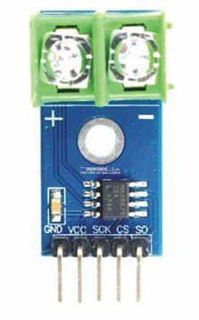
Pin Configuration and Descriptions

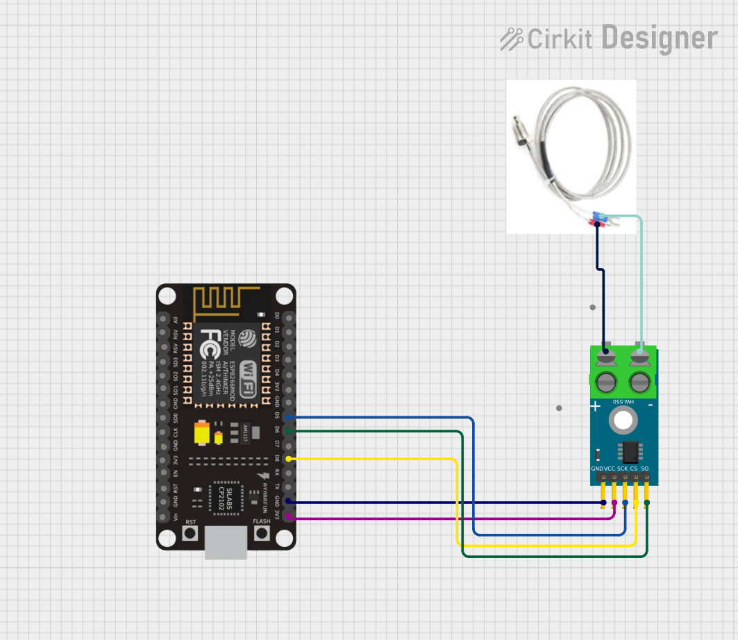
The HW-550 Thermocouple itself does not have pins but is typically connected to an amplifier module (e.g., MAX6675 or MAX31855). Below is the pin configuration for a common thermocouple amplifier module:

Pin Name Description
1 VCC Power supply input (typically 3.3V or 5V)
2 GND Ground connection
3 DO (Data Out) Digital data output for temperature readings
4 CS (Chip Select) Used to select the module when multiple devices are connected to the same bus
5 CLK (Clock) Serial clock input for SPI communication

Usage Instructions

How to Use the HW-550 Thermocouple in a Circuit

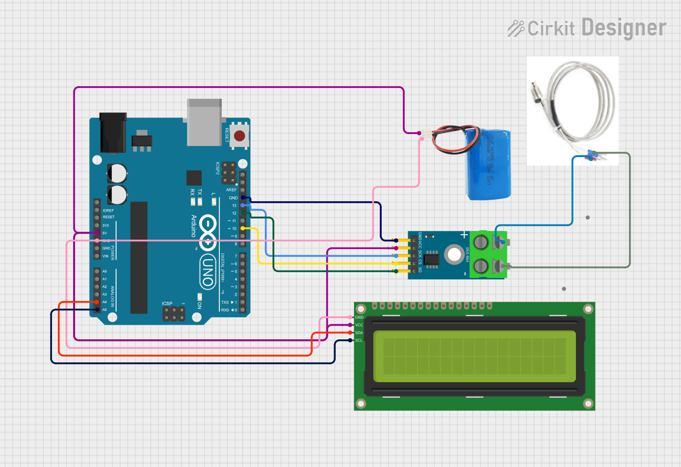
  1. Connect the Thermocouple to an Amplifier Module:

    • Attach the positive (yellow) and negative (red) leads of the thermocouple to the corresponding terminals on the amplifier module.
    • Ensure the connections are secure to avoid signal noise.
  2. Power the Amplifier Module:

    • Connect the VCC pin of the amplifier module to a 3.3V or 5V power source.
    • Connect the GND pin to the ground of your circuit.
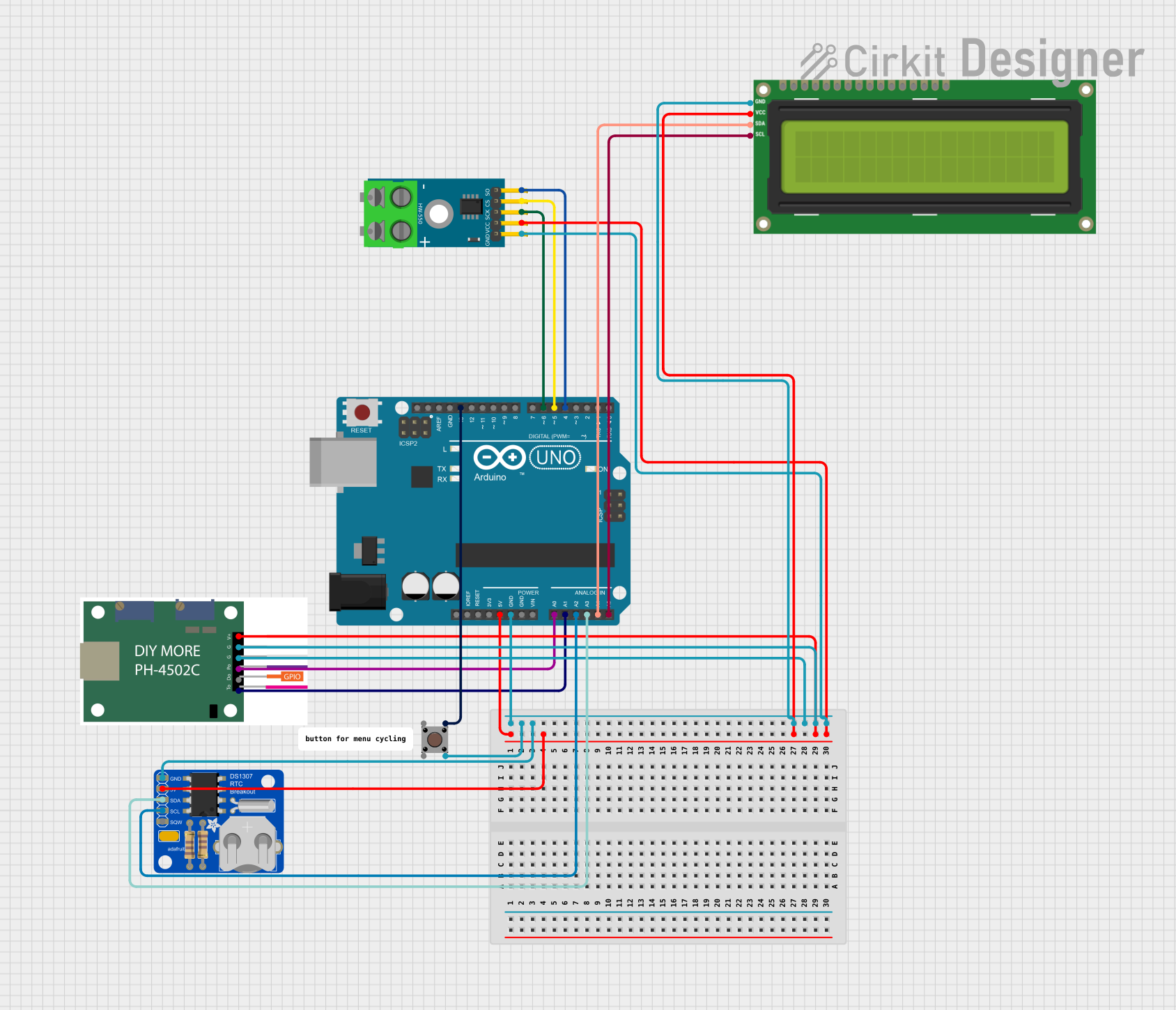
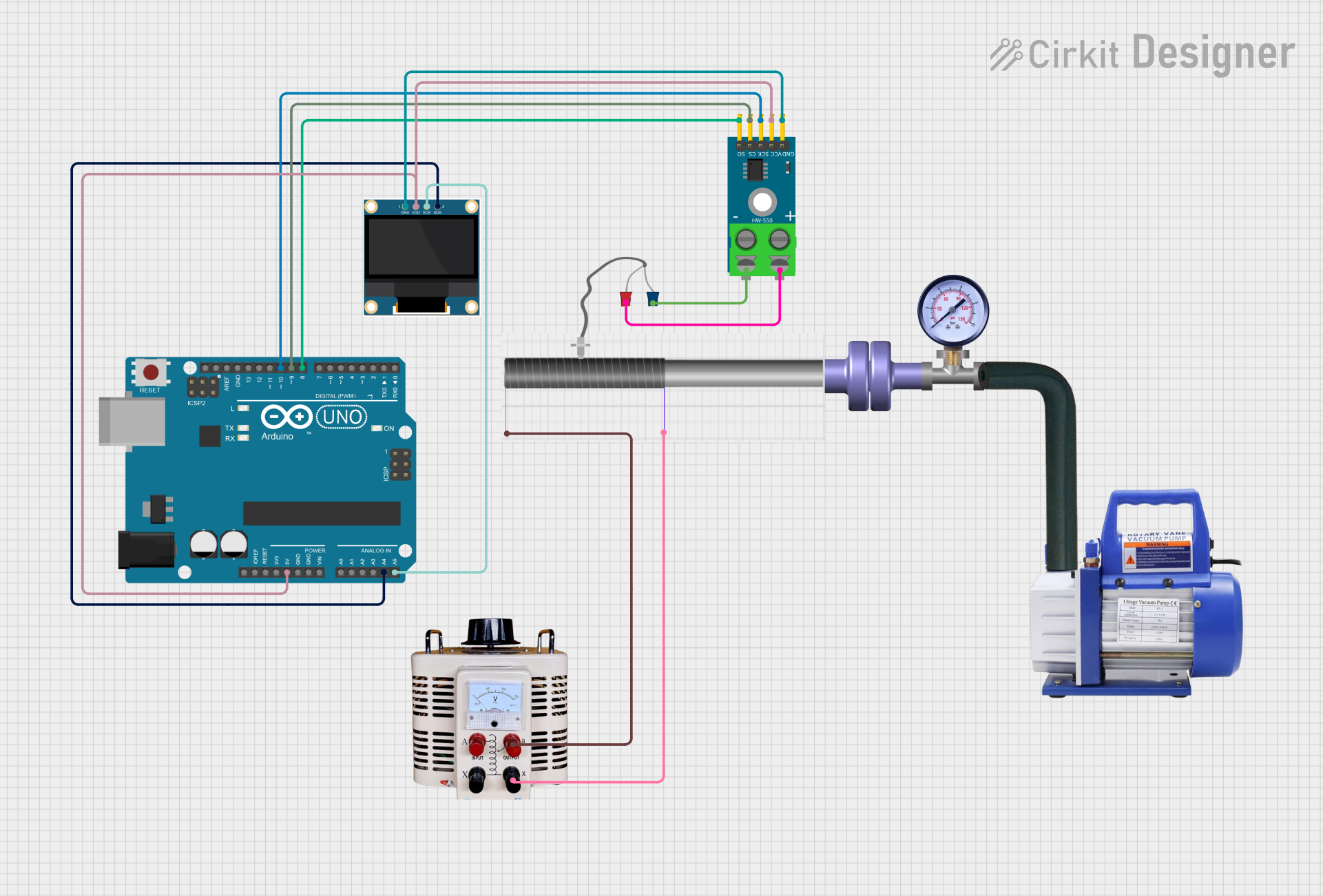
  3. Interface with a Microcontroller:

    • Use SPI communication to connect the amplifier module to a microcontroller (e.g., Arduino UNO).
    • Connect the DO, CS, and CLK pins of the amplifier module to the appropriate digital pins on the microcontroller.
  4. Read Temperature Data:

    • Use a library or write custom code to read the digital temperature data from the amplifier module.

Important Considerations and Best Practices

  • Cold Junction Compensation: Ensure the amplifier module supports cold junction compensation to account for ambient temperature variations.
  • Shielding: Use shielded cables for the thermocouple to minimize electromagnetic interference (EMI).
  • Calibration: Periodically calibrate the thermocouple for accurate readings.
  • Polarity: Always connect the positive and negative leads correctly to avoid incorrect readings.

Example Code for Arduino UNO

Below is an example of how to use the HW-550 Thermocouple with a MAX6675 amplifier module and an Arduino UNO:

#include "max6675.h" // Include the MAX6675 library

// Define the pins connected to the MAX6675 module
int thermoDO = 4;  // Data Out pin
int thermoCS = 5;  // Chip Select pin
int thermoCLK = 6; // Clock pin

// Create a MAX6675 object
MAX6675 thermocouple(thermoCLK, thermoCS, thermoDO);

void setup() {
  Serial.begin(9600); // Initialize serial communication
  Serial.println("HW-550 Thermocouple Test");
  delay(500); // Allow time for the thermocouple to stabilize
}

void loop() {
  // Read the temperature in Celsius
  double temperature = thermocouple.readCelsius();
  
  // Check if the reading is valid
  if (isnan(temperature)) {
    Serial.println("Error: Thermocouple not connected!");
  } else {
    Serial.print("Temperature: ");
    Serial.print(temperature);
    Serial.println(" °C");
  }
  
  delay(1000); // Wait 1 second before the next reading
}

Troubleshooting and FAQs

Common Issues and Solutions

  1. No Temperature Reading or NAN Output:

    • Cause: Loose or incorrect connections.
    • Solution: Verify that the thermocouple leads are securely connected to the amplifier module and that the amplifier is properly powered.
  2. Inaccurate Temperature Readings:

    • Cause: EMI or lack of cold junction compensation.
    • Solution: Use shielded cables and ensure the amplifier module supports cold junction compensation.
  3. Fluctuating Readings:

    • Cause: Electrical noise or unstable power supply.
    • Solution: Add decoupling capacitors near the amplifier module and use a stable power source.
  4. Thermocouple Not Detected:

    • Cause: Damaged thermocouple or incorrect wiring.
    • Solution: Test the thermocouple with a multimeter or replace it if necessary.

FAQs

Q: Can the HW-550 Thermocouple measure negative temperatures?
A: Yes, the HW-550 Thermocouple (Type K) can measure temperatures as low as -200°C.

Q: What is the maximum cable length for the thermocouple?
A: The maximum cable length depends on the environment and signal quality. For long distances, use shielded cables and consider signal amplification.

Q: Can I use the HW-550 Thermocouple without an amplifier module?
A: No, the thermocouple's output voltage is very small and requires an amplifier module for accurate readings.

Q: How do I calibrate the thermocouple?
A: Use a known temperature source (e.g., ice bath or boiling water) and compare the readings. Adjust the calibration settings in your software if necessary.