Cirkit Designer Logo
Cirkit Designer
Your all-in-one circuit design IDE
Home / 
Component Documentation

How to Use Linear Hall Effect Sensor: Examples, Pinouts, and Specs

Image of Linear Hall Effect Sensor
Cirkit Designer LogoDesign with Linear Hall Effect Sensor in Cirkit Designer

Introduction

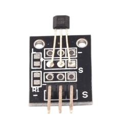
The SS49E Linear Hall Effect Sensor is a versatile device designed to detect the presence and strength of a magnetic field. It produces an analog voltage output that is proportional to the magnetic field strength, making it ideal for applications requiring precise magnetic field measurements. This sensor is widely used in position sensing, current sensing, speed detection, and proximity sensing applications. Its compact size and ease of integration make it a popular choice for both hobbyists and professionals.

Explore Projects Built with Linear Hall Effect Sensor

Use Cirkit Designer to design, explore, and prototype these projects online. Some projects support real-time simulation. Click "Open Project" to start designing instantly!
Magnetic Field-Activated Solenoid Array with Arduino Control
Image of Railgun: A project utilizing Linear Hall Effect Sensor in a practical application
This circuit is designed to use Hall effect sensors for magnetic field detection, interfaced with an Arduino UNO microcontroller to control an array of solenoids through MOSFETs. It includes user interface elements such as a tactile switch and LED, and features flyback diodes for solenoid protection.
Cirkit Designer LogoOpen Project in Cirkit Designer
Arduino Nano ESP32 Hall Sensor Interface with LCD Display
Image of hall effect + speedometer: A project utilizing Linear Hall Effect Sensor in a practical application
This circuit includes a Hall sensor connected to an Arduino Nano ESP32 microcontroller, which is likely used to detect magnetic fields and send the data to the microcontroller on pin D12. The Arduino is also interfaced with an LCD display, with connections for power, ground, control (RS, E), and data (DB4-DB7) to display information. The absence of code suggests that the microcontroller's behavior is not defined in this context, but it is set up to read the Hall sensor and output to the LCD.
Cirkit Designer LogoOpen Project in Cirkit Designer
Arduino Mega 2560 Hall Sensor Interface for Real-Time Magnetic Field Detection
Image of Hall Effect CD: A project utilizing Linear Hall Effect Sensor in a practical application
This circuit uses an Arduino Mega 2560 to read data from a Hall Sensor, which is powered through a terminal block connected to the Arduino's 5V supply. The sensor's ground is connected to the Arduino's ground, and its signal output is read by the Arduino on pin D2.
Cirkit Designer LogoOpen Project in Cirkit Designer
Arduino Nano 33 BLE Magnetic Levitation System with Hall Sensor Feedback and Status LED Indicator
Image of LEVITRON: A project utilizing Linear Hall Effect Sensor in a practical application
This circuit is designed for a magnetic levitation system that uses a Hall sensor to detect magnetic field strength and a TIP120 transistor to control the current through a levitating coil. An Arduino Nano 33 BLE microcontroller reads the sensor and adjusts the coil current via PWM to maintain levitation, while an LED indicates the system's status. The circuit includes power management with 5V DC sources and protective components like diodes and resistors for current control and indication.
Cirkit Designer LogoOpen Project in Cirkit Designer

Explore Projects Built with Linear Hall Effect Sensor

Use Cirkit Designer to design, explore, and prototype these projects online. Some projects support real-time simulation. Click "Open Project" to start designing instantly!
Image of Railgun: A project utilizing Linear Hall Effect Sensor in a practical application
Magnetic Field-Activated Solenoid Array with Arduino Control
This circuit is designed to use Hall effect sensors for magnetic field detection, interfaced with an Arduino UNO microcontroller to control an array of solenoids through MOSFETs. It includes user interface elements such as a tactile switch and LED, and features flyback diodes for solenoid protection.
Cirkit Designer LogoOpen Project in Cirkit Designer
Image of hall effect + speedometer: A project utilizing Linear Hall Effect Sensor in a practical application
Arduino Nano ESP32 Hall Sensor Interface with LCD Display
This circuit includes a Hall sensor connected to an Arduino Nano ESP32 microcontroller, which is likely used to detect magnetic fields and send the data to the microcontroller on pin D12. The Arduino is also interfaced with an LCD display, with connections for power, ground, control (RS, E), and data (DB4-DB7) to display information. The absence of code suggests that the microcontroller's behavior is not defined in this context, but it is set up to read the Hall sensor and output to the LCD.
Cirkit Designer LogoOpen Project in Cirkit Designer
Image of Hall Effect CD: A project utilizing Linear Hall Effect Sensor in a practical application
Arduino Mega 2560 Hall Sensor Interface for Real-Time Magnetic Field Detection
This circuit uses an Arduino Mega 2560 to read data from a Hall Sensor, which is powered through a terminal block connected to the Arduino's 5V supply. The sensor's ground is connected to the Arduino's ground, and its signal output is read by the Arduino on pin D2.
Cirkit Designer LogoOpen Project in Cirkit Designer
Image of LEVITRON: A project utilizing Linear Hall Effect Sensor in a practical application
Arduino Nano 33 BLE Magnetic Levitation System with Hall Sensor Feedback and Status LED Indicator
This circuit is designed for a magnetic levitation system that uses a Hall sensor to detect magnetic field strength and a TIP120 transistor to control the current through a levitating coil. An Arduino Nano 33 BLE microcontroller reads the sensor and adjusts the coil current via PWM to maintain levitation, while an LED indicates the system's status. The circuit includes power management with 5V DC sources and protective components like diodes and resistors for current control and indication.
Cirkit Designer LogoOpen Project in Cirkit Designer

Technical Specifications

The following table outlines the key technical details of the SS49E Linear Hall Effect Sensor:

Parameter Value
Supply Voltage (Vcc) 4.5V to 6V
Output Voltage Range 0.2V to (Vcc - 0.2V)
Sensitivity 1.4 mV/Gauss (typical)
Magnetic Field Range ±1000 Gauss
Operating Temperature -40°C to +100°C
Output Type Analog
Package Type TO-92

Pin Configuration and Descriptions

The SS49E sensor has three pins, as described in the table below:

Pin Number Pin Name Description
1 Vcc Power supply input (4.5V to 6V)
2 GND Ground connection
3 Vout Analog voltage output proportional to magnetic field

Usage Instructions

How to Use the SS49E in a Circuit

  1. Power Supply: Connect the Vcc pin to a 5V power source and the GND pin to the ground of your circuit.
  2. Output Connection: Connect the Vout pin to an analog input pin of a microcontroller (e.g., Arduino UNO) or to an analog-to-digital converter (ADC) for reading the sensor's output.
  3. Magnetic Field Measurement: Place a magnet near the sensor. The output voltage will vary depending on the strength and polarity of the magnetic field:
    • A positive magnetic field (North pole) increases the output voltage.
    • A negative magnetic field (South pole) decreases the output voltage.

Important Considerations and Best Practices

  • Magnetic Field Range: Ensure the magnetic field strength is within the ±1000 Gauss range for accurate readings.
  • Power Supply Stability: Use a stable power supply to avoid noise in the output signal.
  • Placement: Avoid placing the sensor near strong electromagnetic interference (EMI) sources, as this may affect its performance.
  • Filtering: Add a decoupling capacitor (e.g., 0.1 µF) between Vcc and GND to reduce noise.

Example: Using the SS49E with an Arduino UNO

Below is an example code to read the SS49E sensor's output using an Arduino UNO:

// SS49E Linear Hall Effect Sensor Example
// Connect Vcc to 5V, GND to GND, and Vout to A0 on the Arduino UNO

const int sensorPin = A0; // Analog pin connected to SS49E Vout
float sensorValue;        // Variable to store the sensor reading
float voltage;            // Variable to store the calculated voltage

void setup() {
  Serial.begin(9600); // Initialize serial communication at 9600 baud
}

void loop() {
  sensorValue = analogRead(sensorPin); // Read the analog value from the sensor
  voltage = sensorValue * (5.0 / 1023.0); // Convert the reading to voltage
  
  // Print the voltage to the Serial Monitor
  Serial.print("Magnetic Field Voltage: ");
  Serial.print(voltage);
  Serial.println(" V");
  
  delay(500); // Wait for 500ms before the next reading
}

Troubleshooting and FAQs

Common Issues and Solutions

  1. No Output Voltage or Incorrect Readings:

    • Cause: Incorrect wiring or loose connections.
    • Solution: Double-check the wiring and ensure all connections are secure.
  2. Output Voltage is Constant:

    • Cause: The magnetic field is not changing or is outside the sensor's range.
    • Solution: Verify the magnetic field strength and polarity. Use a stronger magnet if necessary.
  3. Noisy Output Signal:

    • Cause: Power supply noise or EMI.
    • Solution: Add a decoupling capacitor (e.g., 0.1 µF) between Vcc and GND. Keep the sensor away from EMI sources.
  4. Sensor Overheating:

    • Cause: Exceeding the maximum supply voltage or operating temperature.
    • Solution: Ensure the supply voltage is within the 4.5V to 6V range and the temperature is within -40°C to +100°C.

FAQs

Q1: Can the SS49E detect both North and South poles of a magnet?
A1: Yes, the SS49E can detect both poles. The output voltage increases for a North pole and decreases for a South pole.

Q2: Can I use the SS49E with a 3.3V microcontroller?
A2: No, the SS49E requires a minimum supply voltage of 4.5V. Use a level shifter or a 5V power source for compatibility.

Q3: How do I calibrate the sensor for precise measurements?
A3: Measure the sensor's output voltage in the absence of a magnetic field (zero Gauss) and use this as the baseline for calibration.

Q4: What is the typical sensitivity of the SS49E?
A4: The typical sensitivity is 1.4 mV/Gauss, but this may vary slightly depending on the operating conditions.

By following this documentation, you can effectively integrate and troubleshoot the SS49E Linear Hall Effect Sensor in your projects.