How to Use LED Panel: Examples, Pinouts, and Specs
Introduction
An LED panel is a flat panel that uses light-emitting diodes (LEDs) as a light source. It is widely used in various applications due to its energy efficiency, brightness, and long lifespan. LED panels are commonly found in display systems, indoor and outdoor lighting, advertising boards, and decorative lighting. Their ability to produce vibrant colors and uniform illumination makes them a popular choice for both functional and aesthetic purposes.
Explore Projects Built with LED Panel


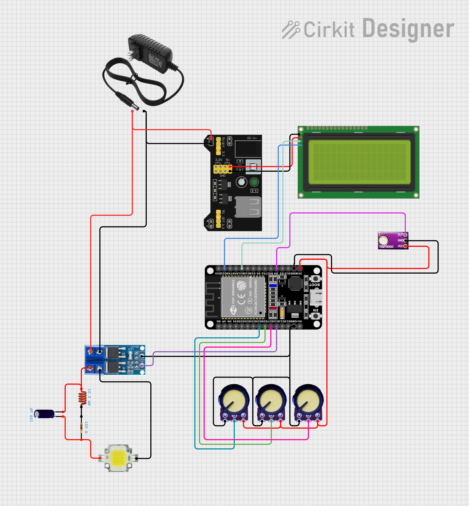
Explore Projects Built with LED Panel
Technical Specifications
Below are the general technical specifications for a standard LED panel. Note that specific values may vary depending on the manufacturer and model.
General Specifications
- Input Voltage: 12V DC or 24V DC (common variants)
- Power Consumption: 10W to 100W (depending on size and brightness)
- Brightness: 1000 to 5000 lumens
- Color Temperature: 2700K (warm white) to 6500K (cool white)
- Lifespan: 30,000 to 50,000 hours
- Viewing Angle: 120° to 180°
- Dimming Capability: Optional (PWM or analog dimming)
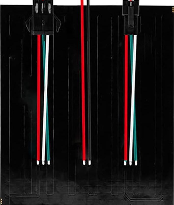
Pin Configuration and Descriptions
The pin configuration of an LED panel depends on its design. Below is a typical configuration for a basic LED panel with a 4-pin connector:
| Pin | Name | Description |
|---|---|---|
| 1 | V+ (Positive) | Positive power supply input (e.g., 12V or 24V DC). |
| 2 | V- (Negative) | Negative power supply input (ground). |
| 3 | DIM (Optional) | Dimming control input (PWM signal or analog voltage, depending on the panel). |
| 4 | NC (No Connect) | Reserved or unused pin (varies by model). |
For RGB LED panels, the pinout may include additional pins for controlling red, green, and blue channels.
| Pin | Name | Description |
|---|---|---|
| 1 | V+ (Positive) | Positive power supply input. |
| 2 | R (Red) | Red channel control input. |
| 3 | G (Green) | Green channel control input. |
| 4 | B (Blue) | Blue channel control input. |
Usage Instructions
How to Use the LED Panel in a Circuit
- Power Supply: Ensure the power supply matches the voltage and current requirements of the LED panel. For example, use a 12V DC adapter for a 12V panel.
- Connections:
- Connect the positive terminal of the power supply to the V+ pin of the LED panel.
- Connect the negative terminal of the power supply to the V- pin of the LED panel.
- If the panel supports dimming, connect a PWM signal or analog voltage to the DIM pin.
- Mounting: Secure the LED panel in its intended location using screws, brackets, or adhesive, ensuring proper heat dissipation.
- Testing: Power on the circuit and verify that the LED panel illuminates as expected.
Important Considerations and Best Practices
- Heat Management: LED panels can generate heat during operation. Ensure proper ventilation or use a heat sink to prevent overheating.
- Voltage Compatibility: Always use a power supply with the correct voltage rating to avoid damaging the panel.
- Dimming: If dimming is required, ensure the dimming controller is compatible with the panel's dimming method (PWM or analog).
- Polarity: Double-check the polarity of the connections to avoid short circuits or damage to the panel.
Example: Controlling an RGB LED Panel with Arduino UNO
Below is an example of how to control an RGB LED panel using an Arduino UNO and PWM signals.
// Define the pins for the RGB channels
const int redPin = 9;    // Red channel connected to PWM pin 9
const int greenPin = 10; // Green channel connected to PWM pin 10
const int bluePin = 11;  // Blue channel connected to PWM pin 11

void setup() {
  // Set the RGB pins as output
  pinMode(redPin, OUTPUT);
  pinMode(greenPin, OUTPUT);
  pinMode(bluePin, OUTPUT);
}

void loop() {
  // Example: Cycle through colors
  setColor(255, 0, 0); // Red
  delay(1000);         // Wait 1 second
  setColor(0, 255, 0); // Green
  delay(1000);         // Wait 1 second
  setColor(0, 0, 255); // Blue
  delay(1000);         // Wait 1 second
}

// Function to set the color of the RGB LED panel
void setColor(int red, int green, int blue) {
  analogWrite(redPin, red);   // Set red intensity (0-255)
  analogWrite(greenPin, green); // Set green intensity (0-255)
  analogWrite(bluePin, blue);  // Set blue intensity (0-255)
}
Troubleshooting and FAQs
Common Issues and Solutions
LED Panel Does Not Light Up:
- Cause: Incorrect power supply voltage or loose connections.
- Solution: Verify the power supply voltage and ensure all connections are secure.
Flickering or Uneven Brightness:
- Cause: Insufficient power supply current or poor dimming signal.
- Solution: Use a power supply with adequate current capacity and check the dimming signal quality.
Overheating:
- Cause: Poor heat dissipation or prolonged operation at maximum brightness.
- Solution: Improve ventilation or reduce brightness to lower heat generation.
Color Mismatch in RGB Panels:
- Cause: Incorrect PWM signal or damaged LED channels.
- Solution: Check the PWM signal values and inspect the panel for damage.
FAQs
Q: Can I use an LED panel outdoors?
- A: Yes, but ensure the panel is rated for outdoor use and is weatherproof.
Q: How do I dim an LED panel?
- A: Use a compatible dimming controller or provide a PWM signal to the DIM pin.
Q: Can I power an LED panel directly from an Arduino?
- A: No, the Arduino cannot supply sufficient current. Use an external power supply and control the panel via transistors or MOSFETs.
This concludes the documentation for the LED panel.