
Cirkit Designer
Your all-in-one circuit design IDE
Home /
Component Documentation
How to Use INA226: Examples, Pinouts, and Specs
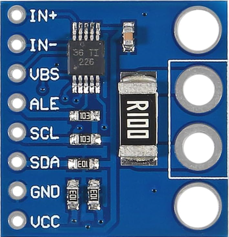
 Design with INA226 in Cirkit Designer
Introduction
The INA226 is a high-side current shunt and power monitor with an integrated precision analog-to-digital converter (ADC) and an I2C-compatible interface. Manufactured by INA, this component is designed to measure voltage, current, and power in a wide range of applications. Its high accuracy and low power consumption make it ideal for battery management systems, power monitoring, and industrial equipment.
Explore Projects Built with INA226
Battery-Powered Load Cell Amplifier with INA125 and LM324
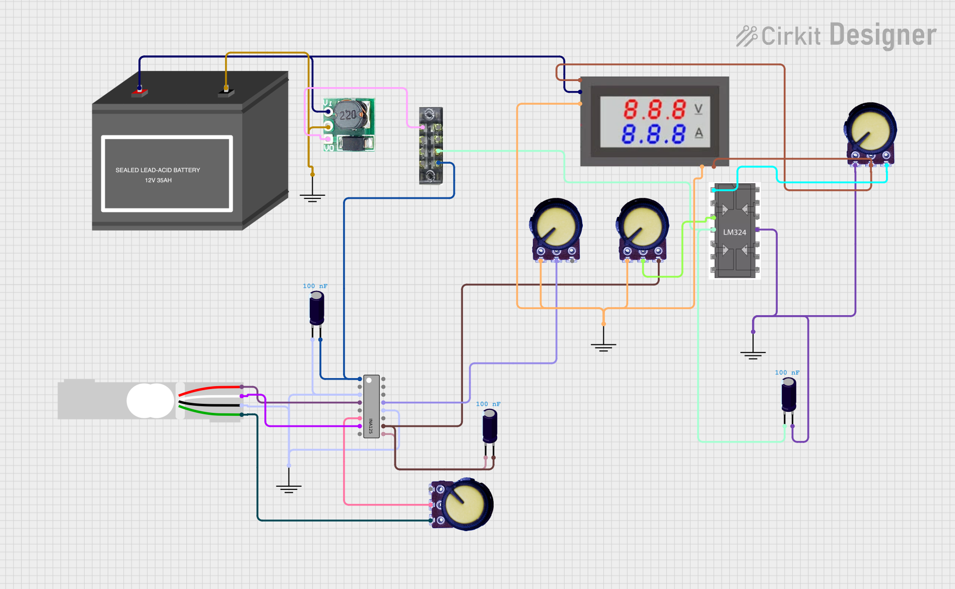
This circuit is a load cell signal conditioning and amplification system. It uses an INA125 instrumentation amplifier to amplify the differential signal from a load cell, with additional filtering and gain control provided by potentiometers and capacitors. The amplified signal is then monitored by a digital voltmeter, and the entire system is powered by a 12V battery with a step-up boost converter to provide stable voltage.
Open Project in Cirkit DesignerESP32-Based Motor Control System with INA219 Current Sensor and ST7735S Display
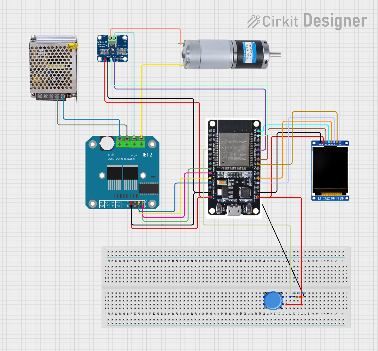
This circuit is a motor control system using an ESP32 microcontroller, an INA219 current sensor, and a BTS7960 motor driver. The ESP32 reads current data from the INA219 and controls the motor driver, while a display module shows relevant information. A pushbutton is included for user interaction.
Open Project in Cirkit DesignerSolar-Powered Environmental Monitoring System with ESP32-C3 and MPPT Charge Control
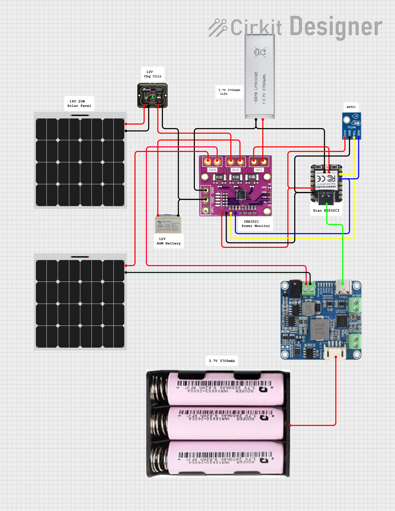
This circuit is designed for solar energy management and monitoring. It includes a 12V AGM battery charged by solar panels through an MPPT charge controller, with voltage monitoring provided by an INA3221 sensor. Additionally, a 3.7V battery is connected to an ESP32-C3 microcontroller and an AHT21 sensor for environmental data collection, with power management handled by a Waveshare Solar Manager.
Open Project in Cirkit DesignerBattery-Powered Emergency Alert System with NUCLEO-F072RB, SIM800L, and GPS NEO 6M

This circuit is an emergency alert system that uses a NUCLEO-F072RB microcontroller to send SMS alerts and make calls via a SIM800L GSM module, while obtaining location data from a GPS NEO 6M module. The system is powered by a Li-ion battery and includes a TP4056 module for battery charging and protection, with a rocker switch to control power to the microcontroller.
Open Project in Cirkit DesignerExplore Projects Built with INA226
Battery-Powered Load Cell Amplifier with INA125 and LM324
This circuit is a load cell signal conditioning and amplification system. It uses an INA125 instrumentation amplifier to amplify the differential signal from a load cell, with additional filtering and gain control provided by potentiometers and capacitors. The amplified signal is then monitored by a digital voltmeter, and the entire system is powered by a 12V battery with a step-up boost converter to provide stable voltage.
Open Project in Cirkit DesignerESP32-Based Motor Control System with INA219 Current Sensor and ST7735S Display
This circuit is a motor control system using an ESP32 microcontroller, an INA219 current sensor, and a BTS7960 motor driver. The ESP32 reads current data from the INA219 and controls the motor driver, while a display module shows relevant information. A pushbutton is included for user interaction.
Open Project in Cirkit DesignerSolar-Powered Environmental Monitoring System with ESP32-C3 and MPPT Charge Control
This circuit is designed for solar energy management and monitoring. It includes a 12V AGM battery charged by solar panels through an MPPT charge controller, with voltage monitoring provided by an INA3221 sensor. Additionally, a 3.7V battery is connected to an ESP32-C3 microcontroller and an AHT21 sensor for environmental data collection, with power management handled by a Waveshare Solar Manager.
Open Project in Cirkit DesignerBattery-Powered Emergency Alert System with NUCLEO-F072RB, SIM800L, and GPS NEO 6M
This circuit is an emergency alert system that uses a NUCLEO-F072RB microcontroller to send SMS alerts and make calls via a SIM800L GSM module, while obtaining location data from a GPS NEO 6M module. The system is powered by a Li-ion battery and includes a TP4056 module for battery charging and protection, with a rocker switch to control power to the microcontroller.
Open Project in Cirkit DesignerCommon Applications
- Battery management systems
- Power supply monitoring
- Server and telecom equipment
- Industrial automation
- Energy metering
Technical Specifications
Key Technical Details
| Parameter | Value |
|---|---|
| Supply Voltage (Vcc) | 2.7V to 5.5V |
| Input Voltage Range | 0V to 36V |
| Current Measurement Range | Determined by external shunt |
| ADC Resolution | 16-bit |
| Communication Interface | I2C (up to 1 MHz) |
| Operating Temperature Range | -40°C to +125°C |
| Power Consumption | 310 µA (typical) |
Pin Configuration and Descriptions
| Pin No. | Pin Name | Description |
|---|---|---|
| 1 | VBUS | Voltage input pin for bus voltage measurement |
| 2 | GND | Ground connection |
| 3 | SCL | I2C clock input |
| 4 | SDA | I2C data input/output |
| 5 | ALERT | Alert output pin for programmable threshold notifications |
| 6 | VIN+ | Positive input for current shunt voltage measurement |
| 7 | VIN- | Negative input for current shunt voltage measurement |
| 8 | VCC | Power supply input |
Usage Instructions
How to Use the INA226 in a Circuit
- Power Supply: Connect the VCC pin to a 2.7V to 5.5V power source and the GND pin to the ground.
- Voltage Measurement: Connect the VBUS pin to the voltage source you want to monitor.
- Current Measurement: Place a shunt resistor between the VIN+ and VIN- pins. The INA226 measures the voltage drop across this resistor to calculate current.
- I2C Communication: Connect the SCL and SDA pins to the corresponding I2C lines of your microcontroller. Use pull-up resistors (typically 4.7 kΩ) on these lines.
- Alert Configuration: Optionally, connect the ALERT pin to a microcontroller GPIO pin to receive threshold alerts.
Important Considerations
- Shunt Resistor Selection: Choose a shunt resistor with a low resistance value to minimize power loss, but ensure it provides a measurable voltage drop for the expected current range.
- I2C Address: The INA226 has a configurable I2C address, allowing multiple devices to share the same bus. Refer to the datasheet for address configuration details.
- Bypass Capacitor: Place a 0.1 µF ceramic capacitor close to the VCC pin to stabilize the power supply.
Example Code for Arduino UNO
Below is an example of how to interface the INA226 with an Arduino UNO to measure voltage and current:
#include <Wire.h>

// INA226 I2C address (default is 0x40, check datasheet for address configuration)
#define INA226_ADDRESS 0x40

// Register addresses
#define REG_BUS_VOLTAGE 0x02
#define REG_CURRENT     0x04

void setup() {
  Wire.begin(); // Initialize I2C communication
  Serial.begin(9600); // Initialize serial communication for debugging

  // Configure INA226 (e.g., calibration register setup)
  Wire.beginTransmission(INA226_ADDRESS);
  Wire.write(0x05); // Calibration register address
  Wire.write(0x10); // Calibration value (example, adjust based on shunt resistor)
  Wire.endTransmission();
}

void loop() {
  float busVoltage = readRegister(REG_BUS_VOLTAGE) * 1.25 / 1000; // Convert to volts
  float current = readRegister(REG_CURRENT) * 0.001; // Convert to amps (example scaling)

  Serial.print("Bus Voltage: ");
  Serial.print(busVoltage);
  Serial.println(" V");

  Serial.print("Current: ");
  Serial.print(current);
  Serial.println(" A");

  delay(1000); // Wait 1 second before next reading
}

uint16_t readRegister(uint8_t reg) {
  Wire.beginTransmission(INA226_ADDRESS);
  Wire.write(reg); // Specify register to read
  Wire.endTransmission();

  Wire.requestFrom(INA226_ADDRESS, 2); // Request 2 bytes
  uint16_t value = Wire.read() << 8 | Wire.read(); // Combine MSB and LSB
  return value;
}
Troubleshooting and FAQs
Common Issues
No I2C Communication:
- Ensure the SCL and SDA lines have proper pull-up resistors (typically 4.7 kΩ).
- Verify the I2C address of the INA226 matches the address in your code.
- Check for loose or incorrect wiring.
Incorrect Voltage or Current Readings:
- Verify the shunt resistor value and ensure it is properly connected.
- Check the calibration register value in the INA226 configuration.
Alert Pin Not Functioning:
- Ensure the ALERT pin is connected to a microcontroller GPIO pin.
- Verify the alert thresholds are correctly configured in the INA226 registers.
Tips for Troubleshooting
- Use an I2C scanner sketch to confirm the INA226 is detected on the I2C bus.
- Double-check all connections and ensure the power supply voltage is within the specified range.
- Consult the INA226 datasheet for detailed register descriptions and configuration options.