How to Use Breadboard NodeMCU: Examples, Pinouts, and Specs
Introduction
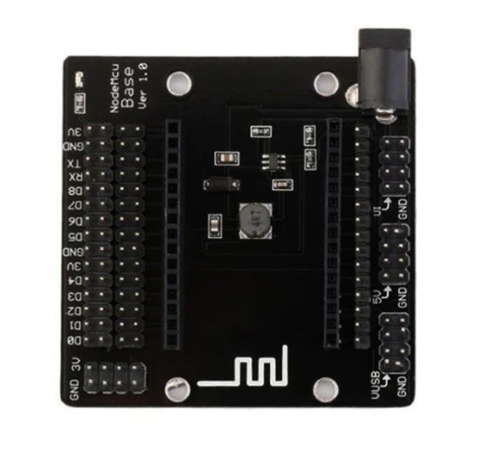
The NodeMCU is an open-source firmware and development kit that helps you to prototype your IoT (Internet of Things) projects with few Lua script lines, or through the Arduino IDE. It includes firmware that runs on the ESP8266 Wi-Fi SoC from Espressif Systems, and hardware which is based on the ESP-12 module. The term "NodeMCU" by default refers to the firmware rather than the development kits. The firmware uses the Lua scripting language.
Common applications of the NodeMCU include smart home devices, IoT sensors, wireless control systems, and various other applications that require communication over Wi-Fi.
Explore Projects Built with Breadboard NodeMCU
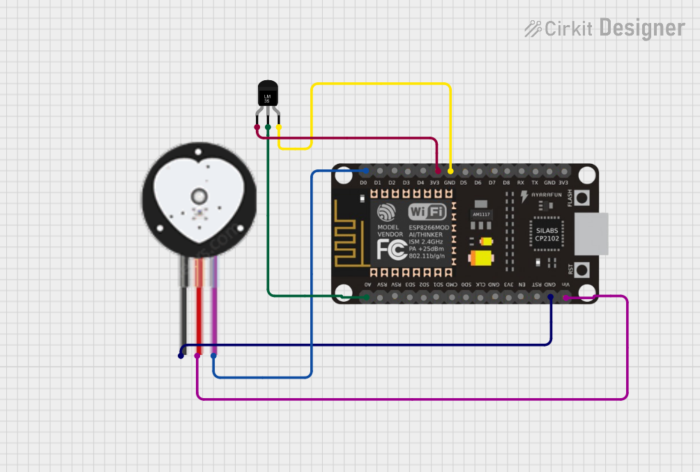
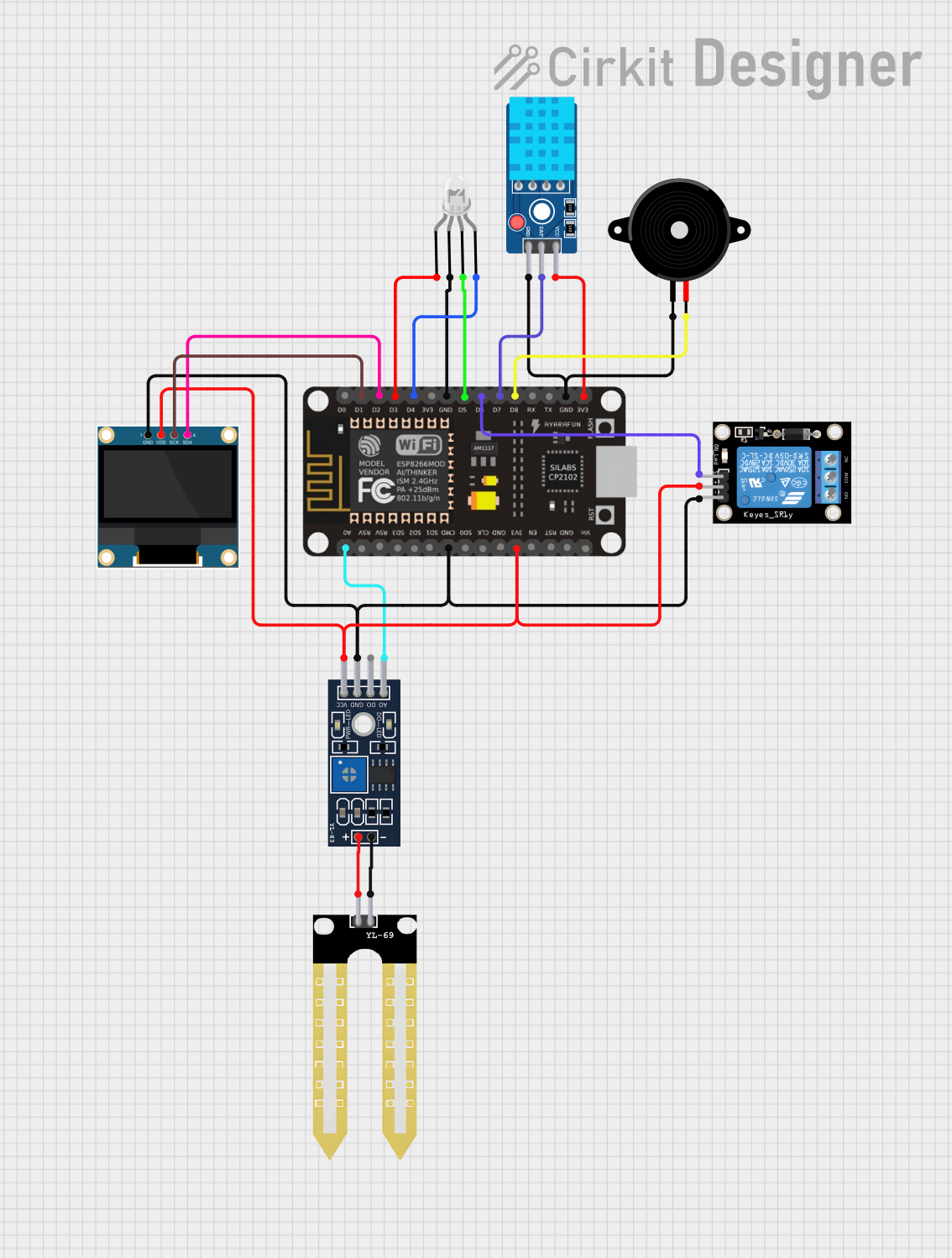
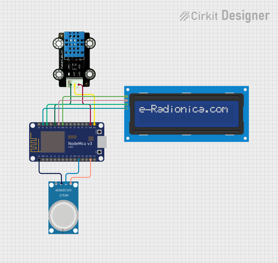

Explore Projects Built with Breadboard NodeMCU
Technical Specifications
Key Technical Details
- Microcontroller: ESP8266
- Operating Voltage: 3.3V
- Input Voltage: 7-12V
- Digital I/O Pins: 11
- Analog Input Pins: 1(Max input: 3.3V)
- Clock Speed: 80MHz/160MHz
- Flash: 4MB
- Wi-Fi Protocol: IEEE 802.11 b/g/n
- Dimensions: 49mm x 24.5mm x 13mm
Pin Configuration and Descriptions
| Pin Number | Function | Description |
|---|---|---|
| D0 | GPIO16 | Digital I/O, PWM, Deep-sleep wake |
| D1 | GPIO5 | Digital I/O, PWM, I2C SCL |
| D2 | GPIO4 | Digital I/O, PWM, I2C SDA |
| D3 | GPIO0 | Digital I/O, PWM, pulled up, boot/flash mode |
| D4 | GPIO2 | Digital I/O, PWM, pulled up, TXD1 |
| D5 | GPIO14 | Digital I/O, PWM, SPI SCK |
| D6 | GPIO12 | Digital I/O, PWM, SPI MISO |
| D7 | GPIO13 | Digital I/O, PWM, SPI MOSI, RXD2 |
| D8 | GPIO15 | Digital I/O, PWM, SPI SS, boot from SD card |
| A0 | ADC0 | Analog Input |
| VIN | - | Input voltage to NodeMCU |
| GND | - | Ground |
| 3V3 | - | 3.3V output |
| RST | - | Reset button |
Usage Instructions
Connecting NodeMCU to a Breadboard
- Insert the NodeMCU into the breadboard, ensuring that the pins are properly seated in the breadboard slots.
- Connect the VIN pin to the positive rail of the breadboard and GND to the negative rail for power distribution.
- Use jumper wires to connect other components to the NodeMCU pins as per your circuit design.
Programming NodeMCU with Arduino IDE
- Install the Arduino IDE from the official Arduino website.
- Open the Arduino IDE, go to File > Preferences, and add the following URL to the Additional Boards Manager URLs:
http://arduino.esp8266.com/stable/package_esp8266com_index.json. - Go to Tools > Board > Boards Manager, search for ESP8266, and install it.
- Select the NodeMCU 1.0 (ESP-12E Module) from Tools > Board menu.
- Choose the correct COM port from Tools > Port.
- Write your code or load an example sketch from File > Examples.
- Click the Upload button to program the NodeMCU.
Example Code
Here is a simple example of blinking an LED connected to the NodeMCU:
// Define the LED pin
const int LED_PIN = D4; // NodeMCU pin where the LED is connected

// the setup function runs once when you press reset or power the board
void setup() {
  // initialize digital pin LED_PIN as an output.
  pinMode(LED_PIN, OUTPUT);
}

// the loop function runs over and over again forever
void loop() {
  digitalWrite(LED_PIN, HIGH);   // turn the LED on (HIGH is the voltage level)
  delay(1000);                   // wait for a second
  digitalWrite(LED_PIN, LOW);    // turn the LED off by making the voltage LOW
  delay(1000);                   // wait for a second
}
Troubleshooting and FAQs
Common Issues
- NodeMCU not detected by computer: Ensure that the USB cable is properly connected and that the drivers are installed.
- Failed to connect to ESP8266: Check if the correct COM port is selected and if the board is correctly configured in the Arduino IDE.
- Sketch upload failure: Verify that the NodeMCU is not in deep-sleep mode and that the correct board settings are used.
Solutions and Tips
- Always use a stable power supply to prevent unexpected resets.
- When using the NodeMCU with a breadboard, be mindful of the 3.3V logic level to prevent damage to the board.
- For deep-sleep functionality, connect GPIO16 (D0) to the RST pin to enable wake-up.
FAQs
Q: Can I use 5V sensors with NodeMCU? A: NodeMCU operates at 3.3V logic levels. For 5V sensors, use a level shifter to prevent damage to the board.
Q: How do I reset the NodeMCU? A: You can reset the NodeMCU by pressing the RST button on the board or by momentarily connecting the RST pin to GND.
Q: How many digital pins can be used for PWM? A: All digital pins on the NodeMCU can be used for PWM except for D0.
Q: What is the maximum current that can be drawn from a single GPIO pin? A: The maximum current from a single GPIO pin should not exceed 12mA.
Q: Can I power NodeMCU using the 3V3 pin? A: Yes, you can power the NodeMCU using the 3V3 pin, but ensure that the power supply is regulated and stable.
For further assistance, consult the NodeMCU community forums or the extensive documentation available online.