How to Use Thermocouple 2 Pins: Examples, Pinouts, and Specs
Introduction
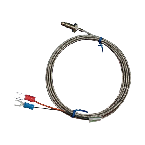
A thermocouple is a temperature-sensing device that operates based on the Seebeck effect, where a voltage is generated due to the temperature difference between two junctions of dissimilar metals. The Thermocouple 2 Pins is a simple and widely used type of thermocouple with two pins for easy connection. It is highly reliable, durable, and suitable for a wide range of temperature measurement applications.
Explore Projects Built with Thermocouple 2 Pins

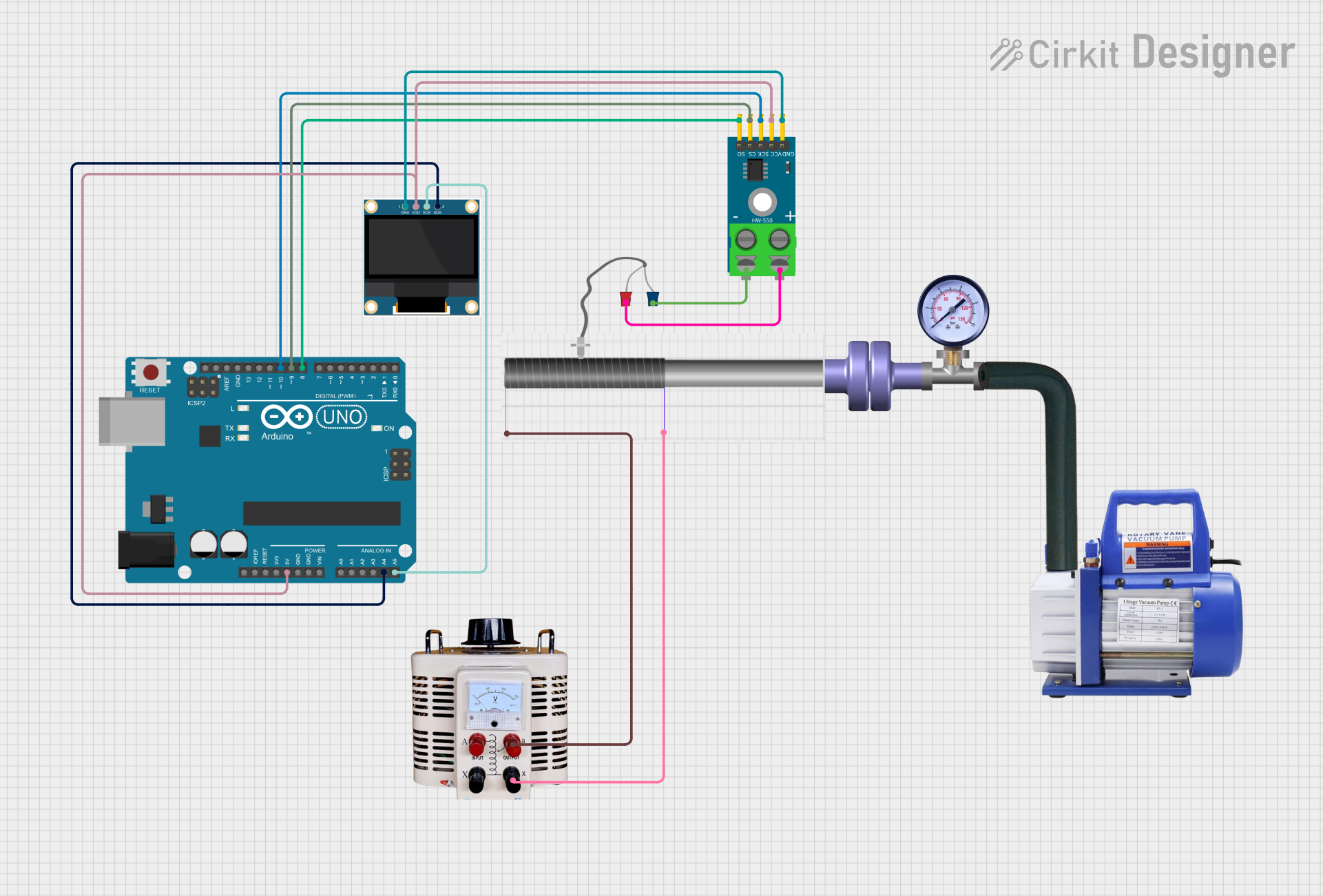
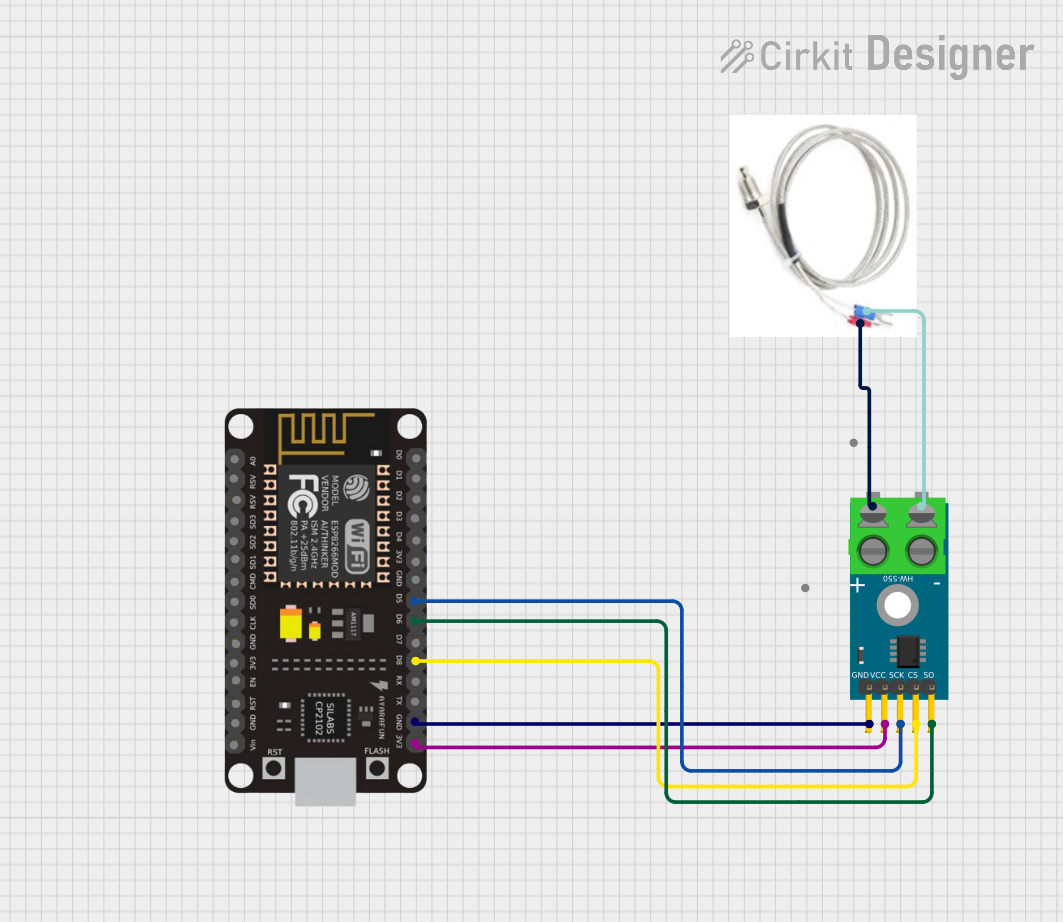
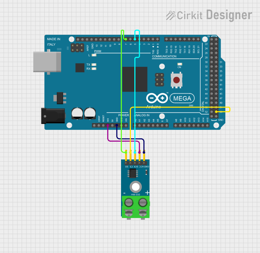
Explore Projects Built with Thermocouple 2 Pins
Common Applications and Use Cases
- Industrial temperature monitoring
- HVAC systems
- Scientific experiments
- Home appliances (e.g., ovens, water heaters)
- Automotive temperature sensing
- Embedded systems and microcontroller-based projects
Technical Specifications
- Type: Varies (commonly Type K, J, or T thermocouples)
- Temperature Range: Depends on the thermocouple type (e.g., Type K: -200°C to 1350°C)
- Accuracy: ±1°C to ±2°C (depending on type and calibration)
- Output Voltage: Microvolts per degree Celsius (e.g., ~41 µV/°C for Type K)
- Material: Dissimilar metals (e.g., Nickel-Chromium and Nickel-Aluminum for Type K)
- Connector Type: 2-pin connection (positive and negative terminals)
Pin Configuration and Descriptions
| Pin Number | Pin Name | Description |
|---|---|---|
| 1 | Positive (+) | Positive terminal of the thermocouple. Typically made of a specific alloy depending on the thermocouple type. |
| 2 | Negative (-) | Negative terminal of the thermocouple. Typically made of a different alloy than the positive terminal. |
Usage Instructions
How to Use the Thermocouple in a Circuit
Connect the Thermocouple to a Signal Amplifier:
Since thermocouples generate very small voltages, you need a thermocouple amplifier (e.g., MAX31855 or MAX6675) to amplify the signal and convert it into a readable format.Connect the Amplifier to a Microcontroller:
Use the amplifier's output to interface with a microcontroller (e.g., Arduino UNO) for temperature readings.Power the Circuit:
Ensure the amplifier and microcontroller are powered according to their specifications.Read and Process the Data:
Use the microcontroller to read the temperature data from the amplifier and display or log it as needed.
Important Considerations and Best Practices
- Cold Junction Compensation: Thermocouples require cold junction compensation to account for the temperature at the connection point. Most amplifiers handle this automatically.
- Polarity: Ensure correct polarity when connecting the thermocouple to the amplifier. Reversing the pins will result in incorrect readings.
- Shielding: Use shielded cables to minimize noise interference, especially in industrial environments.
- Calibration: Regularly calibrate the thermocouple for accurate readings.
- Avoid Overheating: Do not expose the thermocouple to temperatures beyond its specified range, as this can damage the sensor.
Example Code for Arduino UNO
Below is an example of how to use a Type K thermocouple with a MAX6675 amplifier and an Arduino UNO:
#include "max6675.h" // Include the MAX6675 library

// Define the pins connected to the MAX6675 module
int thermoDO = 4;  // Data Out pin
int thermoCS = 5;  // Chip Select pin
int thermoCLK = 6; // Clock pin

// Create a MAX6675 object
MAX6675 thermocouple(thermoCLK, thermoCS, thermoDO);

void setup() {
  Serial.begin(9600); // Initialize serial communication
  Serial.println("Thermocouple Test");
  delay(500); // Allow time for the thermocouple to stabilize
}

void loop() {
  // Read the temperature from the thermocouple
  double temperature = thermocouple.readCelsius();

  // Check if the reading is valid
  if (isnan(temperature)) {
    Serial.println("Error: Thermocouple not connected!");
  } else {
    // Print the temperature in Celsius
    Serial.print("Temperature: ");
    Serial.print(temperature);
    Serial.println(" °C");
  }

  delay(1000); // Wait 1 second before the next reading
}
Troubleshooting and FAQs
Common Issues and Solutions
No Temperature Reading or NAN Output:
- Cause: Loose or incorrect connections.
- Solution: Check all connections, especially the thermocouple pins and amplifier wiring.
Incorrect Temperature Readings:
- Cause: Reversed polarity of the thermocouple pins.
- Solution: Ensure the positive and negative pins are connected correctly.
Fluctuating or Noisy Readings:
- Cause: Electrical noise or interference.
- Solution: Use shielded cables and ensure proper grounding.
Amplifier Not Detected by Microcontroller:
- Cause: Incorrect SPI connections or library issues.
- Solution: Verify the SPI pin connections and ensure the correct library is installed.
FAQs
Q: Can I use the thermocouple without an amplifier?
A: No, the voltage generated by a thermocouple is too small to be directly read by most microcontrollers. An amplifier is required.Q: How do I know which type of thermocouple I have?
A: Check the color coding of the wires or refer to the manufacturer's documentation.Q: Can I extend the thermocouple wires?
A: Yes, but use thermocouple extension wires made of the same material to avoid introducing errors.Q: What is cold junction compensation?
A: It is a method to account for the temperature at the connection point of the thermocouple to the amplifier, ensuring accurate readings.