Cirkit Designer Logo
Cirkit Designer
Your all-in-one circuit design IDE
Home / 
Component Documentation

How to Use RF 433 MHz Transmitter: Examples, Pinouts, and Specs

Image of RF 433 MHz Transmitter
Cirkit Designer LogoDesign with RF 433 MHz Transmitter in Cirkit Designer

Introduction

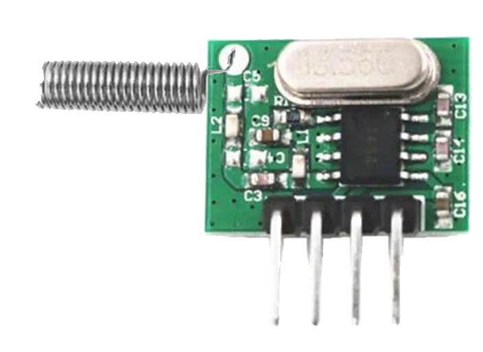
The RF 433 MHz Transmitter is a wireless communication component that operates at a radio frequency of 433 megahertz. It is widely used in remote control systems, home automation, wireless sensor networks, and various DIY projects. The transmitter is capable of sending data over short to medium distances without the need for a direct line of sight, making it a versatile choice for many wireless applications.

Explore Projects Built with RF 433 MHz Transmitter

Use Cirkit Designer to design, explore, and prototype these projects online. Some projects support real-time simulation. Click "Open Project" to start designing instantly!
433 MHz RF Transmitter and Receiver with Arduino UNO for Wireless Communication
Image of Wireless Communication: A project utilizing RF 433 MHz Transmitter in a practical application
This circuit consists of two Arduino UNO microcontrollers, each connected to an RF 433 MHz Transmitter and a 433 MHz RF Receiver Module. The setup allows for wireless communication between the two Arduinos, enabling them to send and receive data over a 433 MHz RF link.
Cirkit Designer LogoOpen Project in Cirkit Designer
433 MHz RF Transmitter and Receiver with Arduino Uno for Wireless LED Control
Image of rf module up: A project utilizing RF 433 MHz Transmitter in a practical application
This circuit consists of two Arduino Uno R3 microcontrollers communicating wirelessly using 433 MHz RF modules. One Arduino is connected to an RF transmitter to send data, while the other Arduino is connected to an RF receiver to receive data and control an LED based on the received signal.
Cirkit Designer LogoOpen Project in Cirkit Designer
Arduino UNO Controlled 433MHz RF Transmitter
Image of Transmitter: A project utilizing RF 433 MHz Transmitter in a practical application
This circuit consists of an Arduino UNO microcontroller connected to a 433MHz RF Transmitter module. The Arduino provides power to the RF Transmitter and is likely to control it via digital pin D12. The purpose of this circuit is to enable wireless communication, with the Arduino controlling the transmission of data through the RF module.
Cirkit Designer LogoOpen Project in Cirkit Designer
ESP32-Based RF Communication System with 433 MHz Modules
Image of 433 mhz: A project utilizing RF 433 MHz Transmitter in a practical application
This circuit comprises an ESP32 microcontroller connected to a 433 MHz RF transmitter and receiver pair. The ESP32 is programmed to receive and decode RF signals through the receiver module, as well as send RF signals via the transmitter module. Additionally, the ESP32 can communicate with a Bluetooth device to exchange commands and data, and it uses an LED for status indication.
Cirkit Designer LogoOpen Project in Cirkit Designer

Explore Projects Built with RF 433 MHz Transmitter

Use Cirkit Designer to design, explore, and prototype these projects online. Some projects support real-time simulation. Click "Open Project" to start designing instantly!
Image of Wireless Communication: A project utilizing RF 433 MHz Transmitter in a practical application
433 MHz RF Transmitter and Receiver with Arduino UNO for Wireless Communication
This circuit consists of two Arduino UNO microcontrollers, each connected to an RF 433 MHz Transmitter and a 433 MHz RF Receiver Module. The setup allows for wireless communication between the two Arduinos, enabling them to send and receive data over a 433 MHz RF link.
Cirkit Designer LogoOpen Project in Cirkit Designer
Image of rf module up: A project utilizing RF 433 MHz Transmitter in a practical application
433 MHz RF Transmitter and Receiver with Arduino Uno for Wireless LED Control
This circuit consists of two Arduino Uno R3 microcontrollers communicating wirelessly using 433 MHz RF modules. One Arduino is connected to an RF transmitter to send data, while the other Arduino is connected to an RF receiver to receive data and control an LED based on the received signal.
Cirkit Designer LogoOpen Project in Cirkit Designer
Image of Transmitter: A project utilizing RF 433 MHz Transmitter in a practical application
Arduino UNO Controlled 433MHz RF Transmitter
This circuit consists of an Arduino UNO microcontroller connected to a 433MHz RF Transmitter module. The Arduino provides power to the RF Transmitter and is likely to control it via digital pin D12. The purpose of this circuit is to enable wireless communication, with the Arduino controlling the transmission of data through the RF module.
Cirkit Designer LogoOpen Project in Cirkit Designer
Image of 433 mhz: A project utilizing RF 433 MHz Transmitter in a practical application
ESP32-Based RF Communication System with 433 MHz Modules
This circuit comprises an ESP32 microcontroller connected to a 433 MHz RF transmitter and receiver pair. The ESP32 is programmed to receive and decode RF signals through the receiver module, as well as send RF signals via the transmitter module. Additionally, the ESP32 can communicate with a Bluetooth device to exchange commands and data, and it uses an LED for status indication.
Cirkit Designer LogoOpen Project in Cirkit Designer

Technical Specifications

Key Technical Details

  • Frequency: 433 MHz
  • Modulation: ASK (Amplitude Shift Keying)
  • Supply Voltage (Vcc): 3V to 12V
  • Operating Current: 9 mA (typical at 5V)
  • Output Power: +10 dBm to +13 dBm (depending on supply voltage)
  • Range: 20-200 meters (environment dependent)

Pin Configuration and Descriptions

Pin Number Name Description
1 Vcc Power supply input (3V to 12V)
2 GND Ground connection
3 DATA Data input for modulation
4 ANT Antenna connection (typically a 17cm wire for 433MHz)

Usage Instructions

How to Use the Component in a Circuit

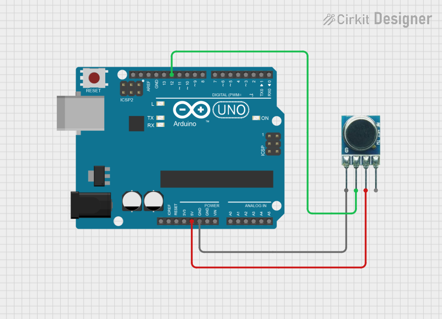
  1. Power Supply: Connect the Vcc pin to a power source within the specified range (3V to 12V). Ensure that the power supply is stable.
  2. Ground: Connect the GND pin to the ground of your power supply and the ground of your data source.
  3. Data Input: Connect the DATA pin to the data output of your encoding device or microcontroller.
  4. Antenna: Attach a 17cm wire to the ANT pin to act as an antenna. The length of the wire is crucial for optimal transmission range and efficiency.

Important Considerations and Best Practices

  • Antenna Length: For best performance, use a quarter-wave monopole antenna, which is approximately 17cm for the 433 MHz frequency.
  • Power Supply: Higher supply voltages within the specified range will result in higher transmission power and range.
  • Data Rate: Keep the data rate low to ensure reliable transmission over longer distances.
  • Interference: Be aware of potential interference from other devices operating at 433 MHz.
  • Regulations: Ensure compliance with local regulations regarding the use of RF transmitters.

Example Arduino UNO Connection and Code

#include <RH_ASK.h>
#include <SPI.h> // Not required, but included for compatibility

// Create ASK object
RH_ASK rf_driver;

void setup()
{
    Serial.begin(9600); // Start serial communication
    if (!rf_driver.init())
        Serial.println("init failed");
}

void loop()
{
    const char *msg = "Hello World";
    rf_driver.send((uint8_t *)msg, strlen(msg));
    rf_driver.waitPacketSent();
    delay(1000); // Wait for a second before next transmission
}

Code Comments

  • RH_ASK rf_driver; creates an instance of the RH_ASK class for handling the RF communication.
  • rf_driver.init() initializes the RF driver and checks if the setup is successful.
  • rf_driver.send((uint8_t *)msg, strlen(msg)); sends the message.
  • rf_driver.waitPacketSent(); waits until the entire message has been sent.
  • delay(1000); pauses the loop for one second before sending the next message.

Troubleshooting and FAQs

Common Issues

  • No Signal: Ensure the antenna is properly connected and is the correct length.
  • Weak Signal: Increase the power supply voltage within the allowed range or reduce the data rate.
  • Interference: Change the location or environment to minimize interference from other devices.

Solutions and Tips

  • Antenna Tuning: Adjust the length of the antenna for optimal performance.
  • Power Supply: Use a regulated power supply to maintain a stable voltage.
  • Data Encoding: Use proper encoding techniques to improve signal integrity.

FAQs

Q: Can I use multiple transmitters in the same area? A: Yes, but ensure they are not transmitting simultaneously to avoid interference.

Q: What is the maximum range I can achieve? A: The range depends on the supply voltage, antenna, environment, and data rate. Under ideal conditions, it can reach up to 200 meters.

Q: Is it legal to use this transmitter? A: It depends on local regulations. Always check your local laws regarding the use of RF transmitters.

Q: Can I connect this transmitter directly to an Arduino? A: Yes, you can connect the DATA pin to an Arduino digital pin and use a library like RadioHead for communication.