How to Use GPS: Examples, Pinouts, and Specs
Introduction
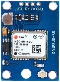
The GPS (Global Positioning System) receiver is an electronic component designed to determine the precise location of an object on Earth. It achieves this by receiving signals from a network of satellites in orbit. GPS receivers are widely used in navigation, tracking, and timing applications, making them an essential component in modern electronics.
Explore Projects Built with GPS


Explore Projects Built with GPS
Common Applications and Use Cases
- Navigation Systems: Used in vehicles, smartphones, and handheld devices for real-time location tracking and route guidance.
- Asset Tracking: Monitoring the location of goods, vehicles, or equipment in logistics and fleet management.
- Geotagging: Adding location metadata to photos, videos, or other digital content.
- Surveying and Mapping: High-precision location data for land surveying and geographic information systems (GIS).
- Timing Applications: Synchronizing clocks in telecommunications, financial systems, and power grids.
Technical Specifications
Below are the key technical details for the GPS receiver:
| Parameter | Value |
|---|---|
| Manufacturer | GPS |
| Manufacturer Part ID | GPS |
| Operating Voltage | 3.3V to 5V |
| Operating Current | 20mA to 50mA |
| Communication Protocol | UART (Serial) |
| Baud Rate | 9600 bps (default, configurable) |
| Position Accuracy | ±2.5 meters (typical) |
| Update Rate | 1 Hz to 10 Hz |
| Operating Temperature | -40°C to +85°C |
| Antenna Type | External or Built-in (varies by model) |
Pin Configuration and Descriptions
The GPS receiver typically has the following pin configuration:
| Pin Name | Pin Number | Description |
|---|---|---|
| VCC | 1 | Power supply input (3.3V to 5V). |
| GND | 2 | Ground connection. |
| TX | 3 | Transmit pin for UART communication. Sends NMEA data to the microcontroller. |
| RX | 4 | Receive pin for UART communication. Receives commands from the microcontroller. |
| PPS | 5 | Pulse-per-second output for precise timing (optional, varies by model). |
Usage Instructions
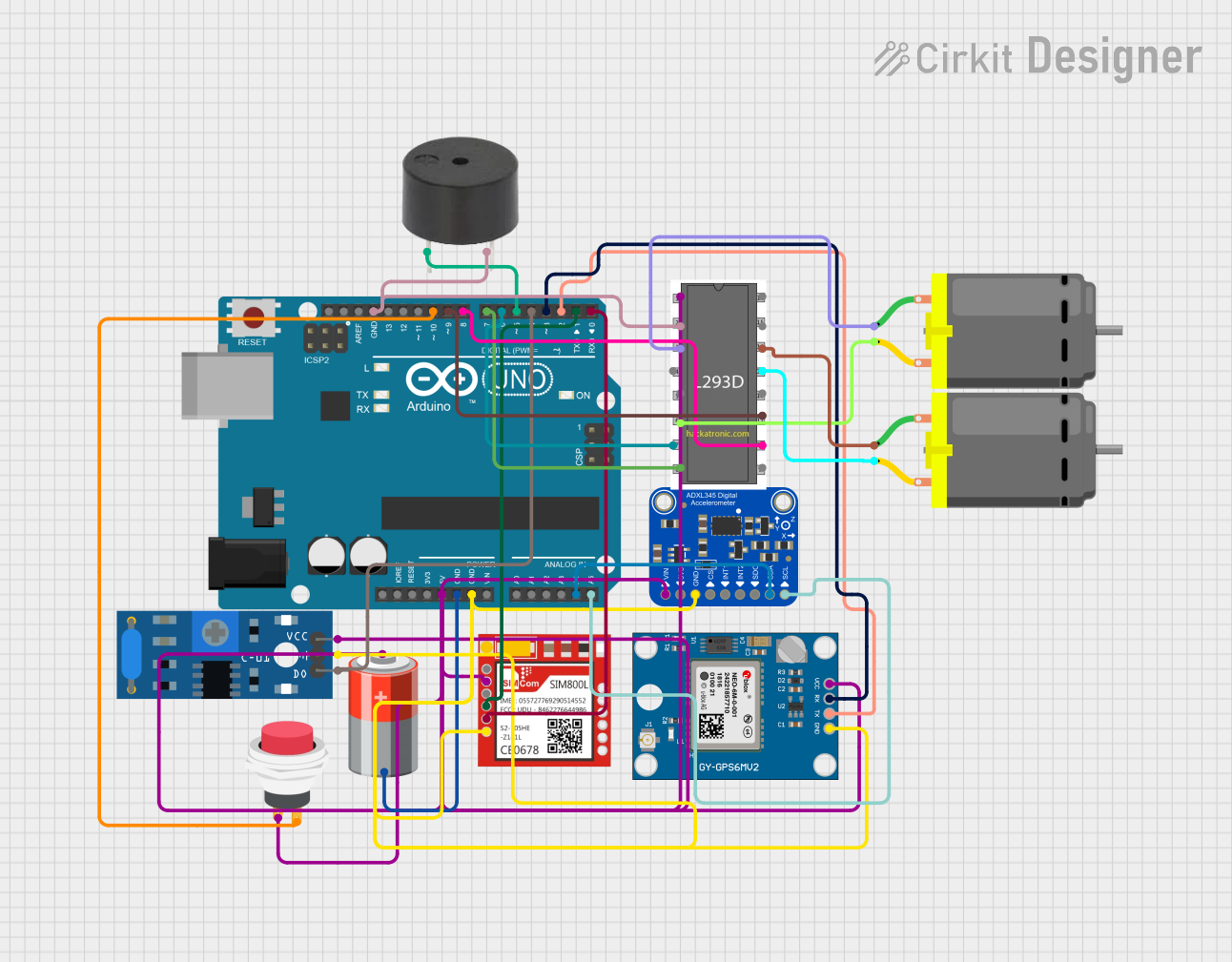
How to Use the GPS Receiver in a Circuit
- Power Supply: Connect the VCC pin to a 3.3V or 5V power source and the GND pin to the ground.
- UART Communication: Connect the TX pin of the GPS module to the RX pin of the microcontroller (e.g., Arduino UNO) and the RX pin of the GPS module to the TX pin of the microcontroller.
- Antenna: If the GPS module requires an external antenna, connect it to the designated antenna port.
- Data Parsing: The GPS module outputs location data in NMEA format. Use a microcontroller or software to parse this data for latitude, longitude, altitude, and other information.
Important Considerations and Best Practices
- Clear View of the Sky: For optimal performance, ensure the GPS module has a clear view of the sky to receive satellite signals.
- Antenna Placement: If using an external antenna, place it in an open area away from obstructions and interference.
- Baud Rate Configuration: The default baud rate is 9600 bps. Configure the microcontroller to match this baud rate for proper communication.
- Power Supply Stability: Use a stable power source to avoid communication errors or module resets.
Example: Connecting GPS to Arduino UNO
Below is an example of how to connect and use the GPS module with an Arduino UNO:
Circuit Connections
- GPS VCC → Arduino 5V
- GPS GND → Arduino GND
- GPS TX → Arduino Digital Pin 4
- GPS RX → Arduino Digital Pin 3
Arduino Code
#include <SoftwareSerial.h>

// Define RX and TX pins for SoftwareSerial
SoftwareSerial gpsSerial(3, 4); // RX = Pin 3, TX = Pin 4

void setup() {
  Serial.begin(9600); // Initialize Serial Monitor at 9600 bps
  gpsSerial.begin(9600); // Initialize GPS module at 9600 bps
  Serial.println("GPS Module Initialized");
}

void loop() {
  // Check if data is available from the GPS module
  while (gpsSerial.available()) {
    char c = gpsSerial.read(); // Read one character from GPS
    Serial.print(c); // Print the character to the Serial Monitor
  }
}
Notes:
- The above code reads raw NMEA data from the GPS module and displays it on the Serial Monitor.
- Use a GPS parsing library (e.g., TinyGPS++) to extract specific data like latitude and longitude.
Troubleshooting and FAQs
Common Issues and Solutions
No GPS Fix (No Location Data)
- Cause: The GPS module cannot lock onto satellite signals.
- Solution: Ensure the module has a clear view of the sky. Move it away from buildings, trees, or other obstructions.
No Data Output
- Cause: Incorrect wiring or baud rate mismatch.
- Solution: Double-check the connections and ensure the microcontroller's baud rate matches the GPS module's baud rate.
Intermittent Data
- Cause: Unstable power supply or interference.
- Solution: Use a stable power source and place the module away from sources of electromagnetic interference.
Garbage Characters in Serial Monitor
- Cause: Incorrect baud rate setting in the Serial Monitor.
- Solution: Set the Serial Monitor baud rate to 9600 bps.
FAQs
Q: Can the GPS module work indoors?
- A: GPS modules generally require a clear view of the sky. Indoors, performance may degrade or fail entirely.
Q: How many satellites are needed for a GPS fix?
- A: A minimum of 4 satellites is required for a 3D fix (latitude, longitude, and altitude).
Q: Can I change the update rate of the GPS module?
- A: Yes, many GPS modules allow you to configure the update rate (e.g., 1 Hz to 10 Hz) using specific commands.
Q: What is NMEA data?
- A: NMEA (National Marine Electronics Association) data is a standard format for GPS data output, including information like latitude, longitude, and time.
This concludes the documentation for the GPS receiver.