Cirkit Designer Logo
Cirkit Designer
Your all-in-one circuit design IDE
Home / 
Component Documentation

How to Use Mono 0.96in 128x64 OLED with STEMMA QT: Examples, Pinouts, and Specs

Image of Mono 0.96in 128x64 OLED with STEMMA QT
Cirkit Designer LogoDesign with Mono 0.96in 128x64 OLED with STEMMA QT in Cirkit Designer

Introduction

The Mono 0.96in 128x64 OLED with STEMMA QT is a compact display module featuring a high-contrast, monochrome OLED screen. With a resolution of 128x64 pixels, this display is capable of presenting text, graphics, and animations with clarity. The inclusion of the STEMMA QT connector simplifies interfacing with microcontrollers, such as the Arduino UNO, allowing for quick and easy prototyping. Common applications include wearable devices, user interfaces, and any project where visual output is required in a small form factor.

Explore Projects Built with Mono 0.96in 128x64 OLED with STEMMA QT

Use Cirkit Designer to design, explore, and prototype these projects online. Some projects support real-time simulation. Click "Open Project" to start designing instantly!
Arduino 101 OLED Display Animation Project
Image of wokwi animater test: A project utilizing Mono 0.96in 128x64 OLED with STEMMA QT in a practical application
This circuit consists of an Arduino 101 microcontroller connected to a 0.96" OLED display via I2C communication. The Arduino runs a program that initializes the OLED and continuously displays an animated sequence of frames on the screen.
Cirkit Designer LogoOpen Project in Cirkit Designer
Arduino Nano and OLED Display for Real-Time Data Visualization
Image of OLED Display: A project utilizing Mono 0.96in 128x64 OLED with STEMMA QT in a practical application
This circuit consists of an Arduino Nano microcontroller connected to a 0.96" OLED display. The Arduino Nano provides power to the OLED display and communicates with it using the I2C protocol via the A4 (SDA) and A5 (SCK) pins.
Cirkit Designer LogoOpen Project in Cirkit Designer
Arduino UNO Based Pong Game with OLED Display and Pushbutton Controls
Image of Sim test OLED Display: A project utilizing Mono 0.96in 128x64 OLED with STEMMA QT in a practical application
This circuit features an Arduino UNO microcontroller connected to an OLED 128x64 I2C Monochrome Display for visual output and two pushbuttons for user input. The Arduino runs a Pong game, with the display showing the game and the pushbuttons used to control the paddle movement. The display is interfaced via I2C (SCL and SDA), and the pushbuttons are connected to digital pins D2 and D3 for input detection.
Cirkit Designer LogoOpen Project in Cirkit Designer
IoT Board with 0.96" OLED Display for Real-Time Data Visualization
Image of dgd: A project utilizing Mono 0.96in 128x64 OLED with STEMMA QT in a practical application
This circuit connects a 0.96" OLED display to an IoT board. The OLED display is powered by the 3.3V and GND pins of the IoT board, and communicates with the board via I2C using the SDA and SCL pins.
Cirkit Designer LogoOpen Project in Cirkit Designer

Explore Projects Built with Mono 0.96in 128x64 OLED with STEMMA QT

Use Cirkit Designer to design, explore, and prototype these projects online. Some projects support real-time simulation. Click "Open Project" to start designing instantly!
Image of wokwi animater test: A project utilizing Mono 0.96in 128x64 OLED with STEMMA QT in a practical application
Arduino 101 OLED Display Animation Project
This circuit consists of an Arduino 101 microcontroller connected to a 0.96" OLED display via I2C communication. The Arduino runs a program that initializes the OLED and continuously displays an animated sequence of frames on the screen.
Cirkit Designer LogoOpen Project in Cirkit Designer
Image of OLED Display: A project utilizing Mono 0.96in 128x64 OLED with STEMMA QT in a practical application
Arduino Nano and OLED Display for Real-Time Data Visualization
This circuit consists of an Arduino Nano microcontroller connected to a 0.96" OLED display. The Arduino Nano provides power to the OLED display and communicates with it using the I2C protocol via the A4 (SDA) and A5 (SCK) pins.
Cirkit Designer LogoOpen Project in Cirkit Designer
Image of Sim test OLED Display: A project utilizing Mono 0.96in 128x64 OLED with STEMMA QT in a practical application
Arduino UNO Based Pong Game with OLED Display and Pushbutton Controls
This circuit features an Arduino UNO microcontroller connected to an OLED 128x64 I2C Monochrome Display for visual output and two pushbuttons for user input. The Arduino runs a Pong game, with the display showing the game and the pushbuttons used to control the paddle movement. The display is interfaced via I2C (SCL and SDA), and the pushbuttons are connected to digital pins D2 and D3 for input detection.
Cirkit Designer LogoOpen Project in Cirkit Designer
Image of dgd: A project utilizing Mono 0.96in 128x64 OLED with STEMMA QT in a practical application
IoT Board with 0.96" OLED Display for Real-Time Data Visualization
This circuit connects a 0.96" OLED display to an IoT board. The OLED display is powered by the 3.3V and GND pins of the IoT board, and communicates with the board via I2C using the SDA and SCL pins.
Cirkit Designer LogoOpen Project in Cirkit Designer

Technical Specifications

Key Technical Details

  • Display Type: Monochrome OLED
  • Screen Size: 0.96 inches
  • Resolution: 128x64 pixels
  • Operating Voltage: 3.3V - 5V
  • Communication Interface: I2C
  • I2C Address: 0x3C (default)
  • Operating Temperature: -40°C to 70°C

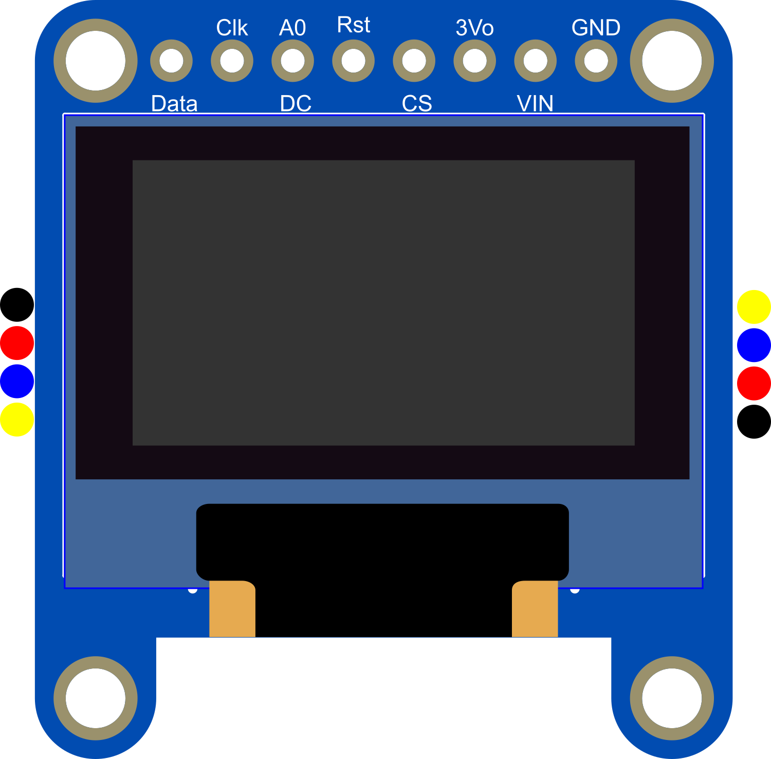
Pin Configuration and Descriptions

Pin Number Pin Name Description
1 GND Ground
2 VCC Power supply (3.3V - 5V)
3 SCL I2C clock line
4 SDA I2C data line
5 RST Reset pin (optional, can be left floating)

Usage Instructions

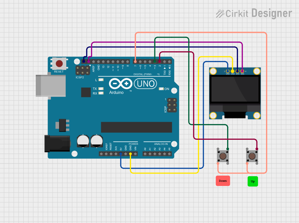
Interfacing with a Circuit

  1. Power Connections: Connect the VCC pin to a 3.3V or 5V power supply, and the GND pin to the ground of your circuit.
  2. Data Connections: Connect the SCL and SDA pins to the corresponding I2C clock and data lines on your microcontroller.
  3. Reset Pin: The RST pin can be connected to a digital pin on your microcontroller if software control of the display reset is required.

Important Considerations and Best Practices

  • Ensure that the power supply voltage matches the requirements of the display to prevent damage.
  • Use pull-up resistors on the I2C lines if they are not already present on the microcontroller board.
  • When using with 5V logic levels, ensure that the I2C lines are level-shifted to be compatible with the display's logic level.

Example Code for Arduino UNO

#include <Wire.h>
#include <Adafruit_GFX.h>
#include <Adafruit_SSD1306.h>

#define SCREEN_WIDTH 128 // OLED display width, in pixels
#define SCREEN_HEIGHT 64 // OLED display height, in pixels

// Declaration for an SSD1306 display connected to I2C (SCL, SDA pins)
#define OLED_RESET     -1 // Reset pin # (or -1 if sharing Arduino reset pin)
Adafruit_SSD1306 display(SCREEN_WIDTH, SCREEN_HEIGHT, &Wire, OLED_RESET);

void setup() {
  // Initialize with the I2C addr 0x3C (for the 128x64)
  if(!display.begin(SSD1306_SWITCHCAPVCC, 0x3C)) {
    Serial.println(F("SSD1306 allocation failed"));
    for(;;); // Don't proceed, loop forever
  }

  // Clear the buffer
  display.clearDisplay();

  // Draw a single pixel in white
  display.drawPixel(10, 10, SSD1306_WHITE);

  // Display the drawing
  display.display();
}

void loop() {
  // Nothing here for this simple example
}

Troubleshooting and FAQs

Common Issues

  • Display Not Powering On: Check the power connections and ensure the voltage is within the specified range.
  • No Display Output: Verify that the I2C connections are correct and that the correct I2C address is being used in the code.
  • Garbled Display: Ensure that the display is properly initialized in your code and that the correct resolution is set.

Solutions and Tips for Troubleshooting

  • Double-check wiring, especially the I2C lines and power connections.
  • Use a multimeter to verify that power is reaching the display module.
  • Check for soldering issues on the STEMMA QT connector.
  • Ensure that the microcontroller's libraries are up to date and compatible with the display.

FAQs

Q: Can I use this display with a 5V microcontroller? A: Yes, but ensure that the I2C lines are level-shifted to be compatible with the display's logic level.

Q: How can I change the I2C address? A: The I2C address can be changed by altering the address jumpers on the back of the display module. Refer to the module's datasheet for details.

Q: What library should I use for this display? A: The Adafruit_SSD1306 library is recommended for use with this display and can be installed via the Arduino Library Manager.