How to Use Modul IR: Examples, Pinouts, and Specs
Introduction
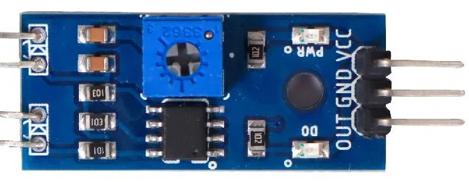
The Modul IR (Manufacturer Part ID: UNO) by Alibaba is an infrared (IR) module designed for transmitting and receiving infrared signals. It is widely used in remote control applications, wireless communication between devices, and proximity detection. This versatile component is ideal for projects involving Arduino, Raspberry Pi, and other microcontroller platforms.
Explore Projects Built with Modul IR

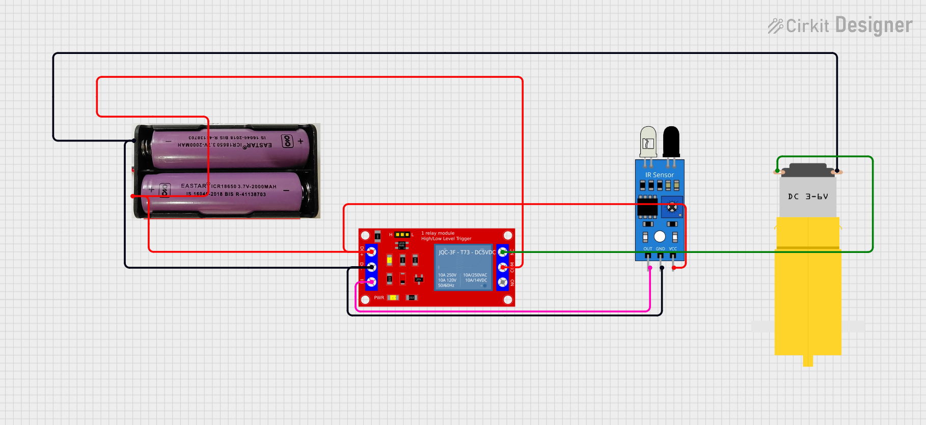
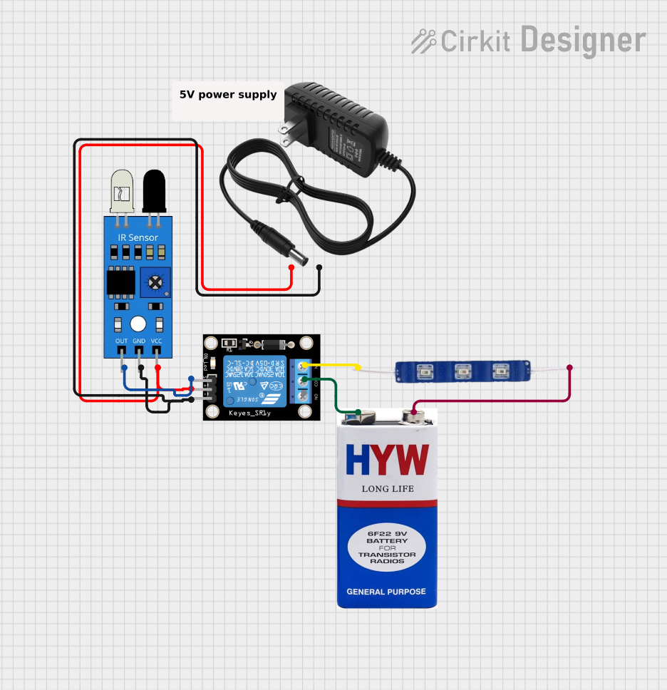
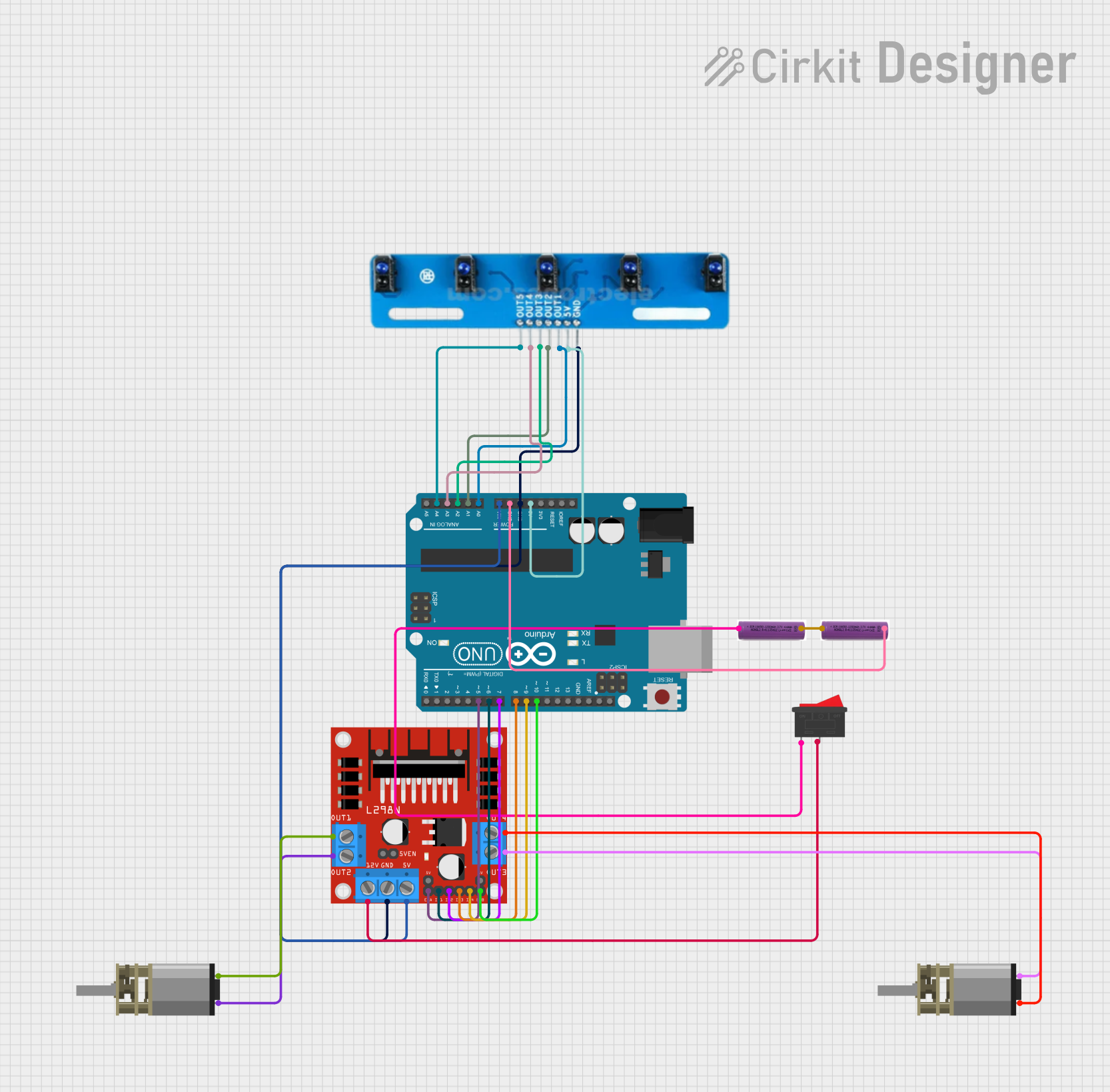
Explore Projects Built with Modul IR
Common Applications and Use Cases
- Remote control systems (e.g., TVs, air conditioners)
- Wireless communication between devices
- Obstacle detection in robotics
- Proximity sensors
- Data transmission in IoT devices
Technical Specifications
The Modul IR is a compact and efficient component with the following technical specifications:
| Parameter | Value |
|---|---|
| Operating Voltage | 3.3V to 5V |
| Operating Current | 20mA (typical) |
| Transmission Range | Up to 10 meters (line of sight) |
| Carrier Frequency | 38 kHz |
| Signal Type | Digital (modulated IR signals) |
| Dimensions | 30mm x 15mm x 10mm |
| Operating Temperature | -20°C to 60°C |
Pin Configuration and Descriptions
The Modul IR typically has three pins for easy integration into circuits:
| Pin | Name | Description |
|---|---|---|
| 1 | VCC | Power supply pin (3.3V to 5V) |
| 2 | GND | Ground connection |
| 3 | OUT | Digital output pin for receiving IR signals |
Usage Instructions
How to Use the Modul IR in a Circuit
- Power the Module: Connect the
VCCpin to a 3.3V or 5V power source and theGNDpin to the ground of your circuit. - Connect the Output: Attach the
OUTpin to a digital input pin of your microcontroller (e.g., Arduino UNO). - Position the Module: Ensure the IR transmitter and receiver have a clear line of sight for optimal performance.
- Program the Microcontroller: Use appropriate libraries or code to send or receive IR signals.
Important Considerations and Best Practices
- Avoid Interference: Ensure the module is not exposed to direct sunlight or other strong light sources, as this can interfere with IR signal transmission.
- Maintain Line of Sight: For best results, keep the transmitter and receiver aligned without obstructions.
- Use a Resistor: If the module is used for continuous transmission, consider adding a current-limiting resistor to protect the IR LED.
- Test the Range: Verify the module's range in your specific environment, as obstacles and ambient light can affect performance.
Example: Using Modul IR with Arduino UNO
Below is an example of how to use the Modul IR with an Arduino UNO to receive IR signals:
#include <IRremote.h> // Include the IRremote library

const int RECV_PIN = 2; // Define the pin connected to the OUT pin of the Modul IR
IRrecv irrecv(RECV_PIN); // Create an IR receiver object
decode_results results;  // Variable to store decoded IR signals

void setup() {
  Serial.begin(9600); // Initialize serial communication
  irrecv.enableIRIn(); // Start the IR receiver
  Serial.println("IR Receiver is ready");
}

void loop() {
  if (irrecv.decode(&results)) { // Check if an IR signal is received
    Serial.print("IR Code: ");
    Serial.println(results.value, HEX); // Print the received IR code in HEX format
    irrecv.resume(); // Prepare to receive the next signal
  }
}
Notes:
- Install the
IRremotelibrary in the Arduino IDE before uploading the code. - Connect the
OUTpin of the Modul IR to digital pin 2 on the Arduino UNO.
Troubleshooting and FAQs
Common Issues and Solutions
No Signal Detected:
- Cause: Incorrect wiring or loose connections.
- Solution: Double-check the connections, ensuring the
VCC,GND, andOUTpins are properly connected.
Short Range or Weak Signal:
- Cause: Obstructions or interference from ambient light.
- Solution: Remove obstacles and avoid direct sunlight or strong artificial light.
Random or Inconsistent Signals:
- Cause: Noise or interference in the circuit.
- Solution: Use a decoupling capacitor (e.g., 10µF) between
VCCandGNDto stabilize the power supply.
IR Code Not Recognized:
- Cause: Incorrect library or incompatible protocol.
- Solution: Ensure the correct library (e.g.,
IRremote) is installed and the protocol matches the transmitting device.
FAQs
Q1: Can the Modul IR be used for bidirectional communication?
A1: No, the Modul IR is designed primarily for unidirectional communication. For bidirectional communication, additional components are required.
Q2: What is the maximum range of the Modul IR?
A2: The maximum range is up to 10 meters in a clear line of sight. However, environmental factors may reduce this range.
Q3: Can I use the Modul IR with a 3.3V microcontroller?
A3: Yes, the Modul IR is compatible with both 3.3V and 5V systems.
Q4: How do I test if the Modul IR is working?
A4: Use a smartphone camera to check if the IR LED emits light when powered. The light will appear as a faint purple glow on the camera screen.
By following this documentation, you can effectively integrate the Modul IR into your projects and troubleshoot any issues that arise.