Cirkit Designer Logo
Cirkit Designer
Your all-in-one circuit design IDE
Home / 
Component Documentation

How to Use Arduino Sensor Shield v5.0: Examples, Pinouts, and Specs

Image of Arduino Sensor Shield v5.0
Cirkit Designer LogoDesign with Arduino Sensor Shield v5.0 in Cirkit Designer

Introduction

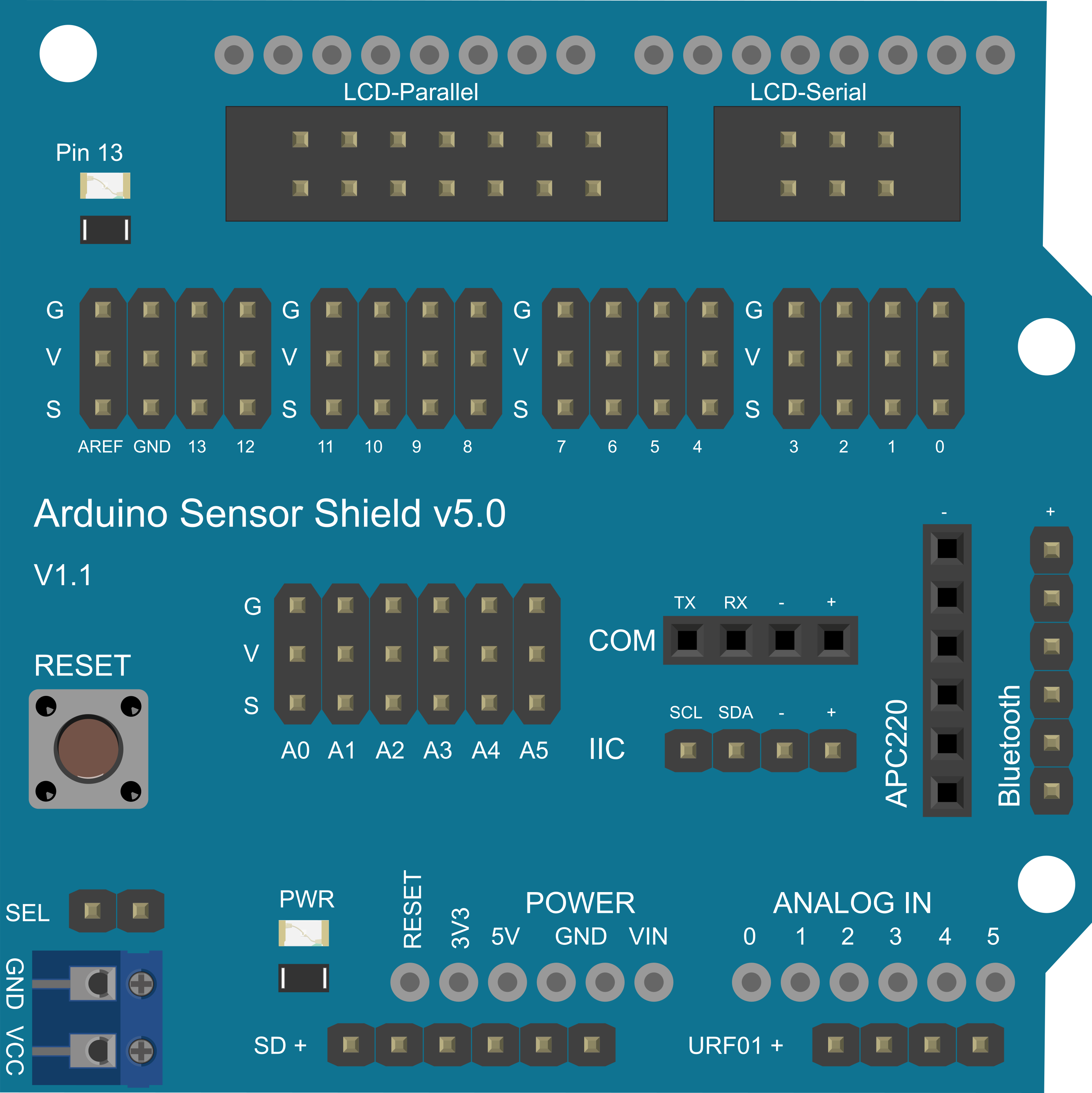
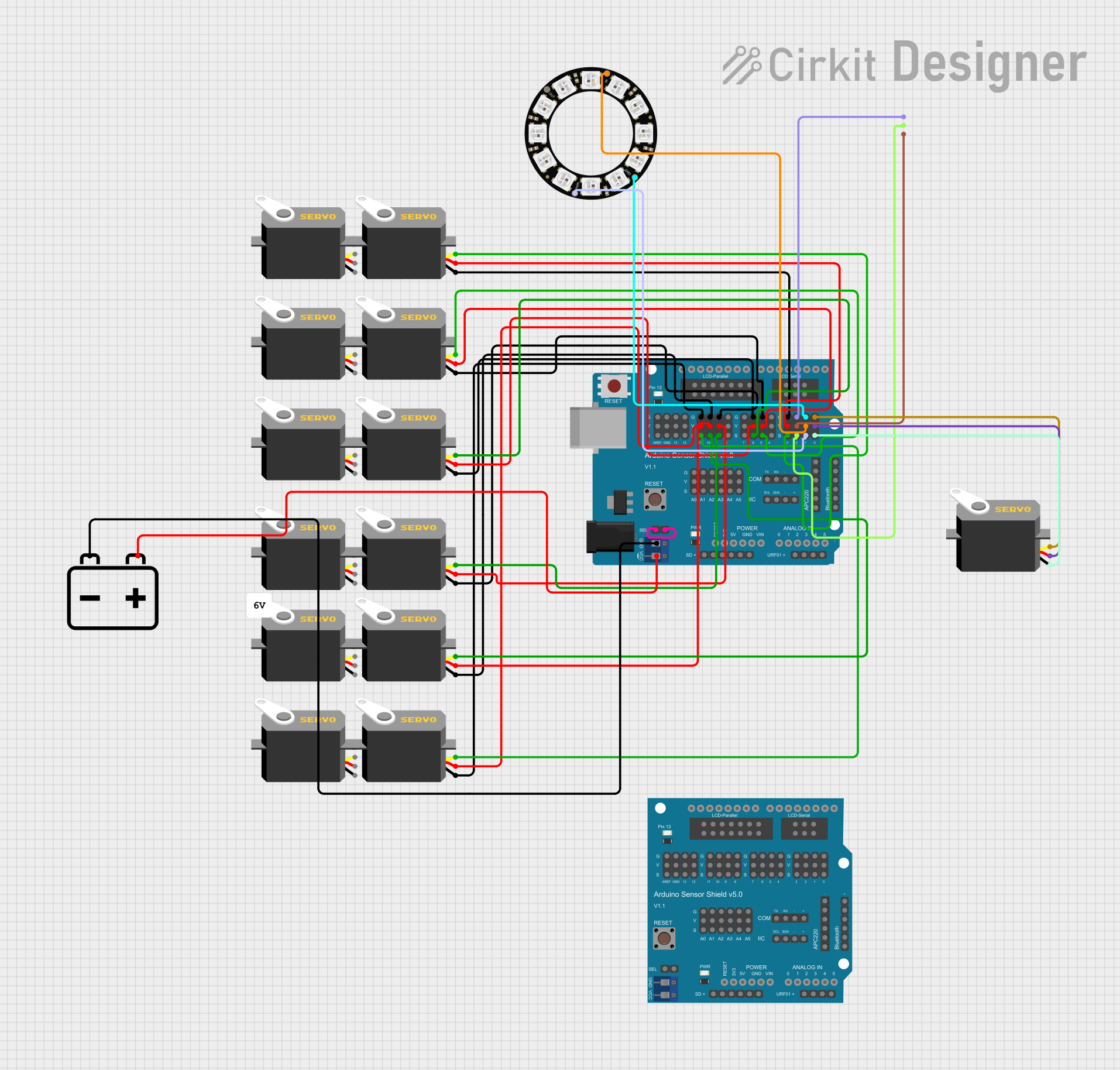
The Arduino Sensor Shield v5.0 is designed to facilitate an easy connection between sensors and Arduino boards. It acts as an interface adapter, allowing for the straightforward integration of various sensors, servos, relays, buttons, and other electronic components without the need for a breadboard or complex wiring. This shield is particularly useful for hobbyists, educators, and prototyping, as it simplifies the process of creating interactive projects.

Explore Projects Built with Arduino Sensor Shield v5.0

Use Cirkit Designer to design, explore, and prototype these projects online. Some projects support real-time simulation. Click "Open Project" to start designing instantly!
Arduino Sensor Shield with I2C LCD and Bluetooth Interface
Image of wallE: A project utilizing Arduino Sensor Shield v5.0 in a practical application
This circuit features an Arduino Sensor Shield v5.0 interfaced with an I2C LCD Display and an HC-05 Bluetooth Module. The LCD Display is connected for power, ground, and I2C communication, allowing it to display data or messages. The HC-05 Bluetooth Module is wired for serial communication with the Arduino Sensor Shield, enabling wireless data exchange with other Bluetooth-enabled devices.
Cirkit Designer LogoOpen Project in Cirkit Designer
Arduino Sensor Shield-Based Smart Home Monitoring System with Bluetooth and I2C LCD
Image of Proyecto final: A project utilizing Arduino Sensor Shield v5.0 in a practical application
This circuit is an environmental monitoring system using an Arduino Sensor Shield. It includes sensors for gas (MQ-2), light (LDR), and temperature (DS18B20), and features a 16x2 I2C LCD for display, an HC-05 Bluetooth module for wireless communication, and a fan motor, buzzer, and LEDs for alert mechanisms.
Cirkit Designer LogoOpen Project in Cirkit Designer
Arduino Sensor Shield-Based Smart Distance and Tilt Detection System with Ultrasonic and IR Sensors
Image of 1207: A project utilizing Arduino Sensor Shield v5.0 in a practical application
This circuit integrates various sensors and actuators with an Arduino Sensor Shield to create an interactive system. It uses an ultrasonic sensor for distance measurement, an IR sensor for object detection, a tilt sensor for orientation detection, and an 8x8 LED matrix for visual feedback. Additionally, it controls a servo motor and a buzzer, responding to sensor inputs and user interactions.
Cirkit Designer LogoOpen Project in Cirkit Designer
Arduino UNO-Based Robotic Arm with Servo Motors and LED Control
Image of asdasd: A project utilizing Arduino Sensor Shield v5.0 in a practical application
This circuit is a robotic control system using an Arduino UNO and a Sensor Shield to manage multiple servos and an LED RGB strip. The Arduino code controls the servos for movement and distance measurement, while the Sensor Shield facilitates power distribution and signal connections.
Cirkit Designer LogoOpen Project in Cirkit Designer

Explore Projects Built with Arduino Sensor Shield v5.0

Use Cirkit Designer to design, explore, and prototype these projects online. Some projects support real-time simulation. Click "Open Project" to start designing instantly!
Image of wallE: A project utilizing Arduino Sensor Shield v5.0 in a practical application
Arduino Sensor Shield with I2C LCD and Bluetooth Interface
This circuit features an Arduino Sensor Shield v5.0 interfaced with an I2C LCD Display and an HC-05 Bluetooth Module. The LCD Display is connected for power, ground, and I2C communication, allowing it to display data or messages. The HC-05 Bluetooth Module is wired for serial communication with the Arduino Sensor Shield, enabling wireless data exchange with other Bluetooth-enabled devices.
Cirkit Designer LogoOpen Project in Cirkit Designer
Image of Proyecto final: A project utilizing Arduino Sensor Shield v5.0 in a practical application
Arduino Sensor Shield-Based Smart Home Monitoring System with Bluetooth and I2C LCD
This circuit is an environmental monitoring system using an Arduino Sensor Shield. It includes sensors for gas (MQ-2), light (LDR), and temperature (DS18B20), and features a 16x2 I2C LCD for display, an HC-05 Bluetooth module for wireless communication, and a fan motor, buzzer, and LEDs for alert mechanisms.
Cirkit Designer LogoOpen Project in Cirkit Designer
Image of 1207: A project utilizing Arduino Sensor Shield v5.0 in a practical application
Arduino Sensor Shield-Based Smart Distance and Tilt Detection System with Ultrasonic and IR Sensors
This circuit integrates various sensors and actuators with an Arduino Sensor Shield to create an interactive system. It uses an ultrasonic sensor for distance measurement, an IR sensor for object detection, a tilt sensor for orientation detection, and an 8x8 LED matrix for visual feedback. Additionally, it controls a servo motor and a buzzer, responding to sensor inputs and user interactions.
Cirkit Designer LogoOpen Project in Cirkit Designer
Image of asdasd: A project utilizing Arduino Sensor Shield v5.0 in a practical application
Arduino UNO-Based Robotic Arm with Servo Motors and LED Control
This circuit is a robotic control system using an Arduino UNO and a Sensor Shield to manage multiple servos and an LED RGB strip. The Arduino code controls the servos for movement and distance measurement, while the Sensor Shield facilitates power distribution and signal connections.
Cirkit Designer LogoOpen Project in Cirkit Designer

Common Applications and Use Cases

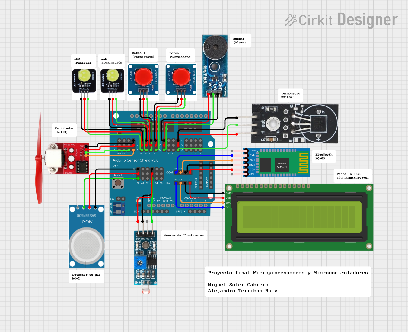
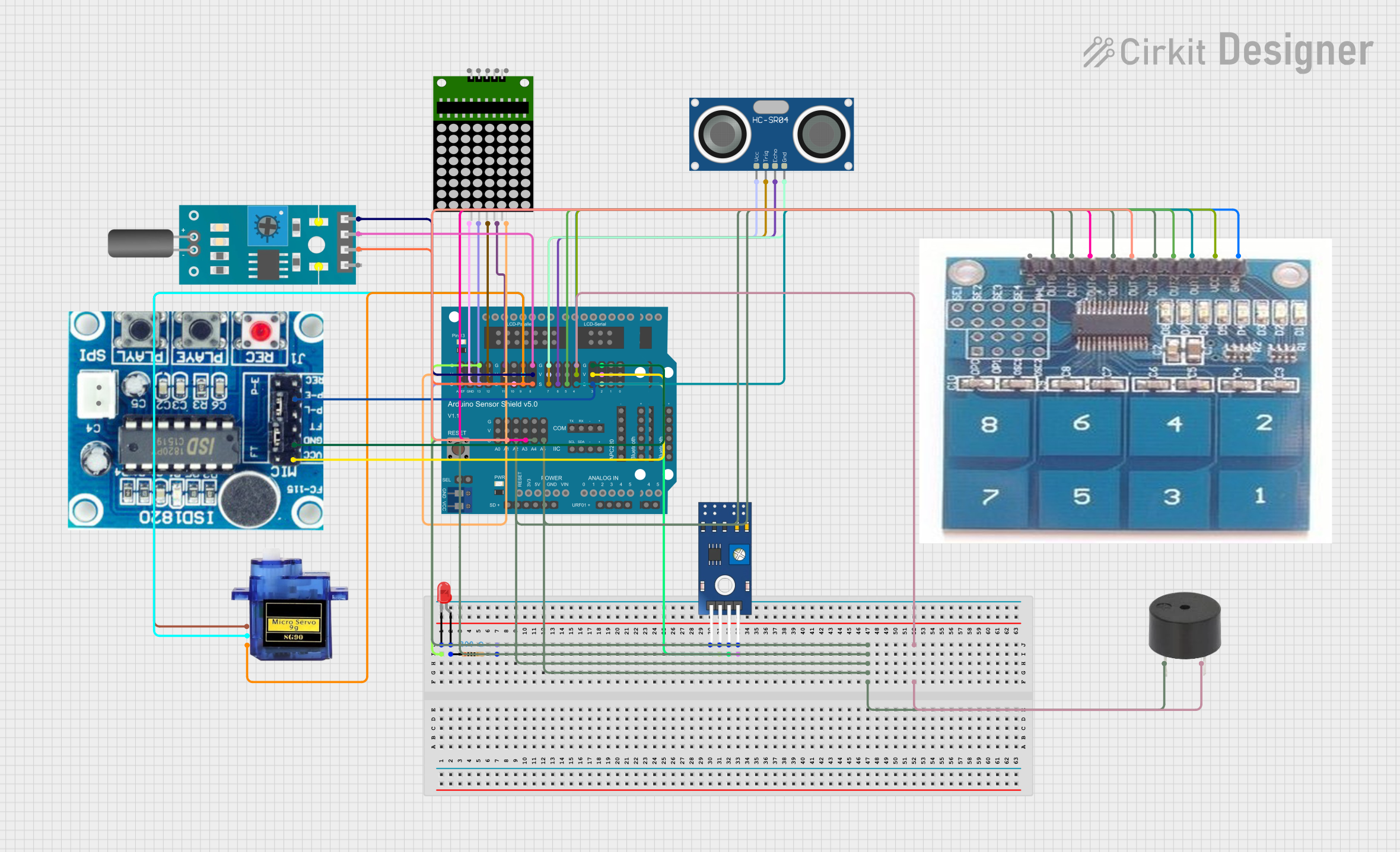
  • Robotics: Connecting multiple servos for robotic arms or vehicles.
  • Environmental Monitoring: Attaching temperature, humidity, and gas sensors.
  • Home Automation: Integrating light, motion, and sound sensors for smart home systems.
  • Educational Projects: Teaching electronics and sensor integration in schools and workshops.

Technical Specifications

Key Technical Details

  • Operating Voltage: 5V (supplied from the Arduino board)
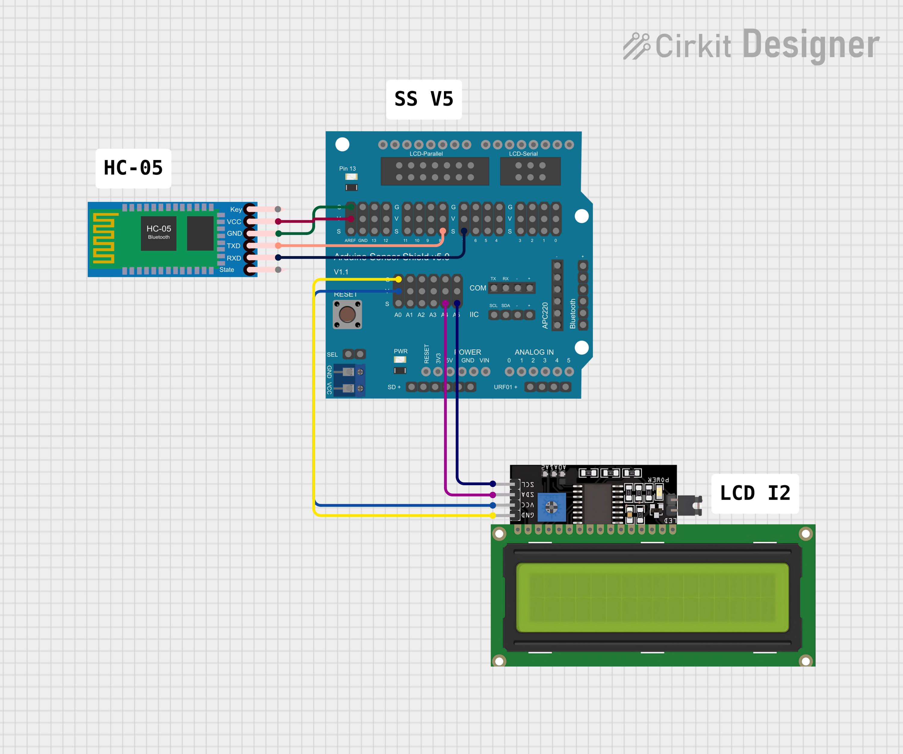
  • I2C Interface: Allows for the connection of I2C devices.
  • Analog Inputs: Multiple analog sensor inputs.
  • Digital IO: Digital input/output pins for various sensors and modules.
  • Servo Motor Connections: Supports up to 12 servo motors.

Pin Configuration and Descriptions

Pin Number Description Type
A0 - A5 Analog sensor inputs Analog In
D0 - D13 Digital input/output pins Digital IO
SDA I2C data line I2C
SCL I2C clock line I2C
V+ Servo power supply (5V from Arduino) Power
GND Ground connection Ground

Usage Instructions

How to Use the Component in a Circuit

  1. Mounting the Shield: Carefully align the Sensor Shield's pins with the headers on the Arduino board and press down to seat it properly.
  2. Connecting Sensors: Plug your sensors into the designated analog or digital ports on the shield. Ensure that the sensor's voltage and current requirements are compatible with the shield's specifications.
  3. Powering Servos: Connect the servo motors to the shield's servo ports. The power for the servos is typically drawn from the Arduino's 5V pin, but for multiple servos or high-power servos, an external power supply is recommended.

Important Considerations and Best Practices

  • Power Supply: Ensure that the power supply to the Arduino is sufficient to handle the connected sensors and servos. Overloading the Arduino's voltage regulator can lead to damage.
  • I2C Devices: When connecting I2C devices, make sure to avoid address conflicts by configuring each device with a unique address if possible.
  • Analog Sensors: For accurate readings, keep the wires between analog sensors and the shield as short as possible to minimize noise and interference.

Troubleshooting and FAQs

Common Issues Users Might Face

  • Inaccurate Sensor Readings: This can be caused by noise or interference. Use shielded cables for analog sensors and keep the wiring short.
  • Servo Jitter: If the servos are jittering, it may be due to an inadequate power supply. Consider using an external power source for the servos.
  • I2C Communication Failure: Ensure that there are pull-up resistors on the I2C lines if required, and check for correct wiring and unique I2C addresses.

Solutions and Tips for Troubleshooting

  • Check Connections: Verify that all sensors and components are properly connected to the shield and that there are no loose connections.
  • Power Supply: Use a multimeter to check the voltage levels at the power rails of the shield to ensure they are within the expected range.
  • Isolate the Problem: Disconnect all sensors and reconnect them one at a time to identify the component causing the issue.

FAQs

Q: Can I use the Sensor Shield v5.0 with all Arduino boards? A: The Sensor Shield v5.0 is compatible with Arduino UNO and other boards with the same pinout, such as the Arduino Mega 2560.

Q: How many sensors can I connect to the Sensor Shield v5.0? A: You can connect as many sensors as there are available input pins, keeping in mind the power limitations of your Arduino board.

Q: Do I need to install any libraries to use the Sensor Shield v5.0? A: No additional libraries are required for the shield itself, but you may need specific libraries for the sensors you are using.

Example Code for Arduino UNO

Here is a simple example of how to read an analog sensor connected to the Sensor Shield v5.0:

// Define the analog sensor pin
const int sensorPin = A0; // Connected to the A0 pin on the Sensor Shield

void setup() {
  // Initialize serial communication at 9600 bits per second:
  Serial.begin(9600);
}

void loop() {
  // Read the value from the sensor:
  int sensorValue = analogRead(sensorPin);
  // Print out the value to the serial monitor
  Serial.println(sensorValue);
  delay(1000); // Wait for 1 second between readings
}

Remember to adjust sensorPin to match the actual pin your sensor is connected to on the Sensor Shield.