Cirkit Designer Logo
Cirkit Designer
Your all-in-one circuit design IDE
Home / 
Component Documentation

How to Use SN74HC193N FIAX: Examples, Pinouts, and Specs

Image of SN74HC193N FIAX
Cirkit Designer LogoDesign with SN74HC193N FIAX in Cirkit Designer

Introduction

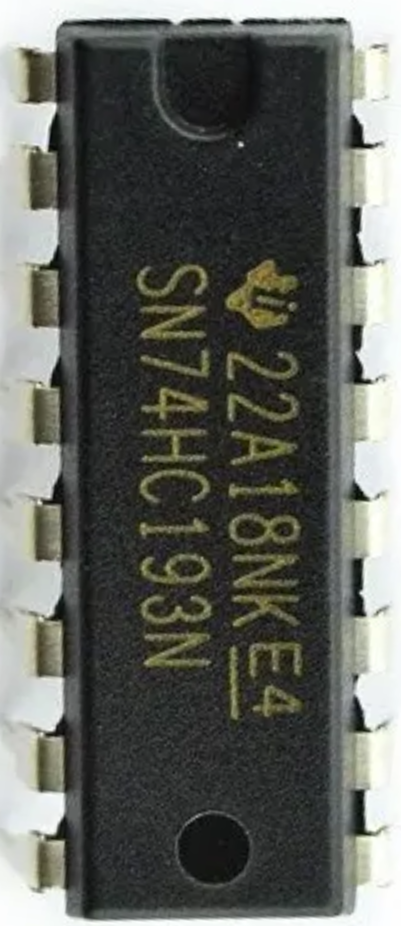
The SN74HC193N FIAX is a high-speed, 4-bit binary up/down synchronous counter. This versatile component is widely used in digital electronics for counting applications, such as frequency division, event counting, and time measurement. It features a wide operating voltage range and low power consumption, making it suitable for various applications in both consumer and industrial electronics.

Explore Projects Built with SN74HC193N FIAX

Use Cirkit Designer to design, explore, and prototype these projects online. Some projects support real-time simulation. Click "Open Project" to start designing instantly!
STM32 and Arduino UNO Based Dual RS485 Communication Interface
Image of STM to Arduino RS485: A project utilizing SN74HC193N FIAX in a practical application
This circuit consists of two microcontrollers, an STM32F103C8T6 and an Arduino UNO, each interfaced with separate RS485 transceiver modules for serial communication. The STM32F103C8T6 controls the RE (Receiver Enable) and DE (Driver Enable) pins of one RS485 module to manage its operation, and communicates via the A9 and A10 pins for DI (Data Input) and RO (Receiver Output), respectively. The Arduino UNO is similarly connected to another RS485 module, with digital pins D2 and D3 interfacing with DI and RO, and D8 controlling both RE and DE. The RS485 modules are connected to each other through their A and B differential communication lines, enabling serial data exchange between the two microcontrollers over a robust and long-distance capable RS485 network.
Cirkit Designer LogoOpen Project in Cirkit Designer
STM32-Controlled LED Display with 74HC595 Shift Register and 12-Bit DAC
Image of Harry Stim Breadboard: A project utilizing SN74HC193N FIAX in a practical application
This circuit uses a 74HC595 shift register to control multiple LEDs via a common ground configuration, with a microcontroller providing serial data input. It includes decoupling capacitors for stability and a 12-Bit DAC, potentially for analog signal generation or reference voltage application.
Cirkit Designer LogoOpen Project in Cirkit Designer
Arduino-Controlled 74HC595 Shift Register LED Driver
Image of cube: A project utilizing SN74HC193N FIAX in a practical application
This circuit consists of multiple 74HC595 shift registers daisy-chained together, controlled by an Arduino UNO. The shift registers are used to expand the number of digital outputs from the Arduino, allowing for control of multiple outputs with only a few pins. The circuit likely drives an array of LEDs or similar devices, as indicated by the series resistors connected to the outputs of the shift registers.
Cirkit Designer LogoOpen Project in Cirkit Designer
Teensy 4.0 and MAX7219-Based 7-Segment Display Counter
Image of dispay: A project utilizing SN74HC193N FIAX in a practical application
This circuit uses a Teensy 4.0 microcontroller to control a MAX7219 LED driver, which in turn drives three 7-segment displays. The microcontroller runs code to display numbers from 0 to 999 on the 7-segment displays, with the SN74AHCT125N buffer providing signal integrity and the necessary capacitors and resistors ensuring stable operation.
Cirkit Designer LogoOpen Project in Cirkit Designer

Explore Projects Built with SN74HC193N FIAX

Use Cirkit Designer to design, explore, and prototype these projects online. Some projects support real-time simulation. Click "Open Project" to start designing instantly!
Image of STM to Arduino RS485: A project utilizing SN74HC193N FIAX in a practical application
STM32 and Arduino UNO Based Dual RS485 Communication Interface
This circuit consists of two microcontrollers, an STM32F103C8T6 and an Arduino UNO, each interfaced with separate RS485 transceiver modules for serial communication. The STM32F103C8T6 controls the RE (Receiver Enable) and DE (Driver Enable) pins of one RS485 module to manage its operation, and communicates via the A9 and A10 pins for DI (Data Input) and RO (Receiver Output), respectively. The Arduino UNO is similarly connected to another RS485 module, with digital pins D2 and D3 interfacing with DI and RO, and D8 controlling both RE and DE. The RS485 modules are connected to each other through their A and B differential communication lines, enabling serial data exchange between the two microcontrollers over a robust and long-distance capable RS485 network.
Cirkit Designer LogoOpen Project in Cirkit Designer
Image of Harry Stim Breadboard: A project utilizing SN74HC193N FIAX in a practical application
STM32-Controlled LED Display with 74HC595 Shift Register and 12-Bit DAC
This circuit uses a 74HC595 shift register to control multiple LEDs via a common ground configuration, with a microcontroller providing serial data input. It includes decoupling capacitors for stability and a 12-Bit DAC, potentially for analog signal generation or reference voltage application.
Cirkit Designer LogoOpen Project in Cirkit Designer
Image of cube: A project utilizing SN74HC193N FIAX in a practical application
Arduino-Controlled 74HC595 Shift Register LED Driver
This circuit consists of multiple 74HC595 shift registers daisy-chained together, controlled by an Arduino UNO. The shift registers are used to expand the number of digital outputs from the Arduino, allowing for control of multiple outputs with only a few pins. The circuit likely drives an array of LEDs or similar devices, as indicated by the series resistors connected to the outputs of the shift registers.
Cirkit Designer LogoOpen Project in Cirkit Designer
Image of dispay: A project utilizing SN74HC193N FIAX in a practical application
Teensy 4.0 and MAX7219-Based 7-Segment Display Counter
This circuit uses a Teensy 4.0 microcontroller to control a MAX7219 LED driver, which in turn drives three 7-segment displays. The microcontroller runs code to display numbers from 0 to 999 on the 7-segment displays, with the SN74AHCT125N buffer providing signal integrity and the necessary capacitors and resistors ensuring stable operation.
Cirkit Designer LogoOpen Project in Cirkit Designer

Technical Specifications

Key Technical Details

Parameter Value
Manufacturer Texas Instruments
Part Number SN74HC193N FIAX
Supply Voltage (Vcc) 2V to 6V
Input Voltage 0V to Vcc
Output Voltage 0V to Vcc
High-Level Input Voltage (VIH) 2V (min) to 6V (max)
Low-Level Input Voltage (VIL) 0V (min) to 1.5V (max)
High-Level Output Current (IOH) -4mA
Low-Level Output Current (IOL) 4mA
Operating Temperature Range -40°C to 85°C
Propagation Delay (typical) 15ns

Pin Configuration and Descriptions

Pin No. Pin Name Description
1 MR Master Reset (active low)
2 CPD Clock Pulse Down
3 CPU Clock Pulse Up
4 Q1 Output Bit 1
5 Q2 Output Bit 2
6 Q3 Output Bit 3
7 Q4 Output Bit 4
8 GND Ground
9 TCUP Terminal Count Up
10 TCDN Terminal Count Down
11 PE Parallel Enable (active low)
12 P0 Parallel Data Input Bit 0
13 P1 Parallel Data Input Bit 1
14 P2 Parallel Data Input Bit 2
15 P3 Parallel Data Input Bit 3
16 Vcc Supply Voltage

Usage Instructions

How to Use the SN74HC193N FIAX in a Circuit

  1. Power Supply: Connect the Vcc pin (16) to a power supply within the range of 2V to 6V. Connect the GND pin (8) to the ground of the power supply.
  2. Clock Inputs: Use the CPU (3) and CPD (2) pins to provide clock pulses for counting up and down, respectively.
  3. Reset: To reset the counter, apply a low signal to the MR (1) pin.
  4. Parallel Load: To load a parallel value into the counter, apply a low signal to the PE (11) pin and provide the desired value on the P0 (12), P1 (13), P2 (14), and P3 (15) pins.
  5. Outputs: The current count value can be read from the Q1 (4), Q2 (5), Q3 (6), and Q4 (7) pins.

Important Considerations and Best Practices

  • Debouncing: Ensure that the clock inputs (CPU and CPD) are debounced to avoid erroneous counting due to noise or mechanical switch bounce.
  • Power Supply Decoupling: Use a decoupling capacitor (e.g., 0.1µF) close to the Vcc pin to filter out noise from the power supply.
  • Unused Inputs: Tie any unused inputs to a defined logic level (either Vcc or GND) to prevent floating inputs, which can cause unpredictable behavior.

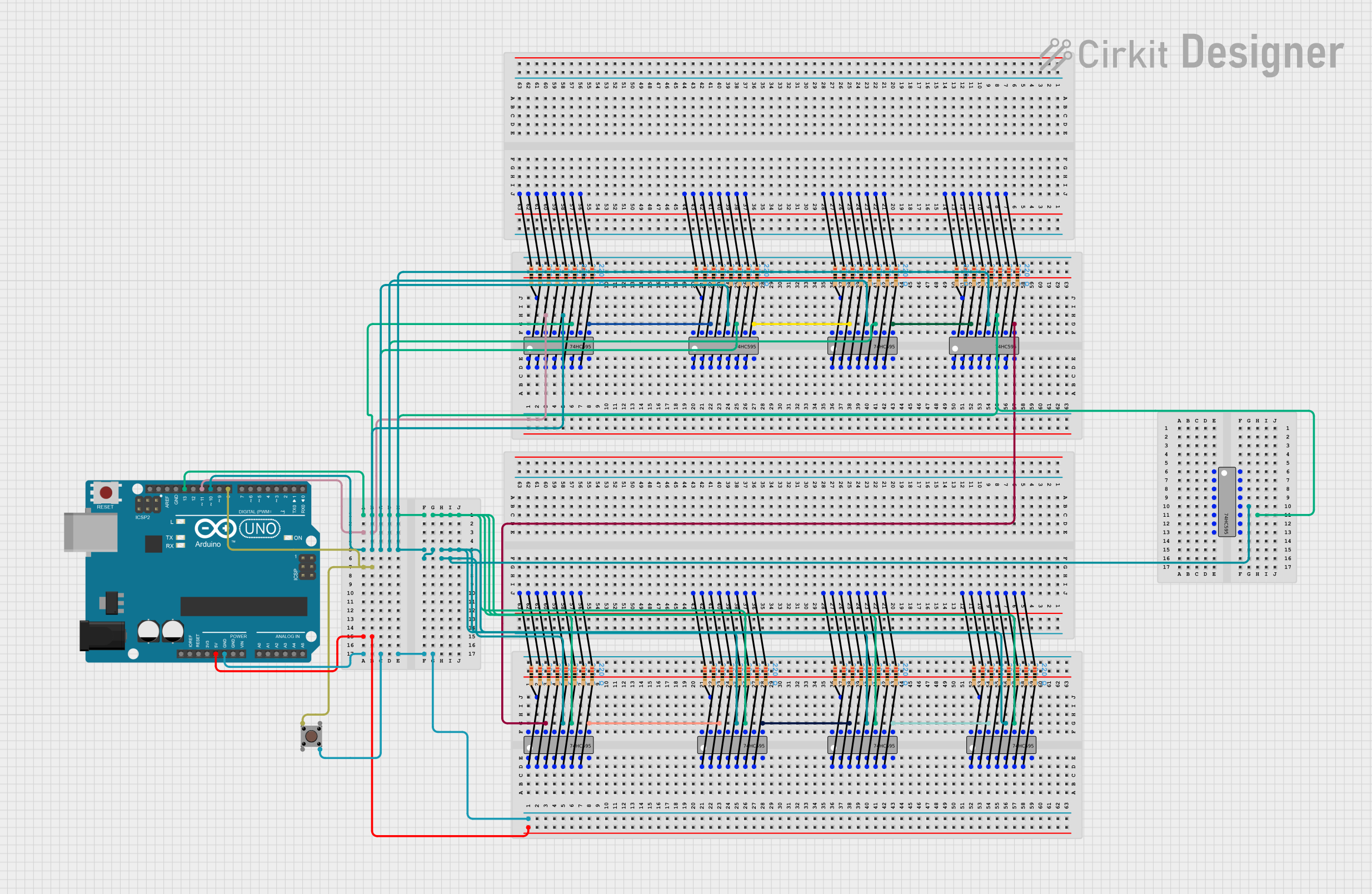
Example Circuit with Arduino UNO

/*
  Example code to interface SN74HC193N FIAX with Arduino UNO
  This code increments the counter every second and prints the count
  to the serial monitor.
*/

const int clockUpPin = 2;  // Pin connected to CPU (Clock Pulse Up)
const int resetPin = 3;    // Pin connected to MR (Master Reset)
const int q1Pin = 4;       // Pin connected to Q1 (Output Bit 1)
const int q2Pin = 5;       // Pin connected to Q2 (Output Bit 2)
const int q3Pin = 6;       // Pin connected to Q3 (Output Bit 3)
const int q4Pin = 7;       // Pin connected to Q4 (Output Bit 4)

void setup() {
  pinMode(clockUpPin, OUTPUT);
  pinMode(resetPin, OUTPUT);
  pinMode(q1Pin, INPUT);
  pinMode(q2Pin, INPUT);
  pinMode(q3Pin, INPUT);
  pinMode(q4Pin, INPUT);

  Serial.begin(9600);

  // Reset the counter
  digitalWrite(resetPin, LOW);
  delay(10);
  digitalWrite(resetPin, HIGH);
}

void loop() {
  // Generate a clock pulse to increment the counter
  digitalWrite(clockUpPin, HIGH);
  delay(10);
  digitalWrite(clockUpPin, LOW);

  // Read the counter value
  int count = (digitalRead(q4Pin) << 3) |
              (digitalRead(q3Pin) << 2) |
              (digitalRead(q2Pin) << 1) |
              digitalRead(q1Pin);

  // Print the count to the serial monitor
  Serial.print("Count: ");
  Serial.println(count);

  delay(1000);  // Wait for 1 second
}

Troubleshooting and FAQs

Common Issues and Solutions

  1. Counter Not Incrementing/Decrementing:

    • Solution: Ensure that the clock pulses are correctly applied to the CPU or CPD pins. Check for proper debouncing of the clock signals.
  2. Unexpected Count Values:

    • Solution: Verify that all input pins are connected to defined logic levels. Floating inputs can cause unpredictable behavior.
  3. Counter Resets Unexpectedly:

    • Solution: Check the MR pin to ensure it is not being inadvertently pulled low. Ensure stable power supply and proper decoupling.

FAQs

Q1: Can I use the SN74HC193N FIAX with a 3.3V power supply?

  • A1: Yes, the SN74HC193N FIAX can operate with a supply voltage range of 2V to 6V, so 3.3V is within the acceptable range.

Q2: How can I cascade multiple SN74HC193N FIAX counters for higher bit counts?

  • A2: Connect the terminal count output (TCUP or TCDN) of the first counter to the clock input (CPU or CPD) of the next counter. This way, the second counter will increment/decrement when the first counter overflows/underflows.

Q3: What is the maximum counting frequency of the SN74HC193N FIAX?

  • A3: The maximum counting frequency is determined by the propagation delay, which is typically 15ns. This translates to a maximum frequency of approximately 66.7MHz.

By following this documentation, users can effectively integrate the SN74HC193N FIAX into their projects, ensuring reliable and accurate counting operations.