How to Use Step-Up Converter: Examples, Pinouts, and Specs
Introduction
The Step-Up Converter (ELC-X0122), manufactured by Custom Thermoelectric, is a DC-DC boost converter designed to increase an input voltage to a higher output voltage while maintaining power balance. This component is widely used in applications where a higher voltage is required from a lower voltage source, such as in battery-powered devices, renewable energy systems, and portable electronics.
Explore Projects Built with Step-Up Converter


Explore Projects Built with Step-Up Converter
Common Applications and Use Cases
- Powering high-voltage devices from low-voltage batteries
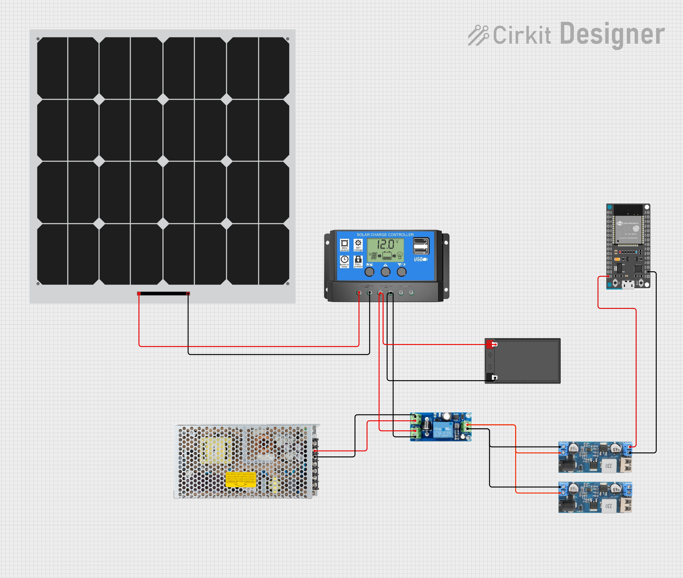
- Solar energy systems to step up panel voltage
- LED drivers requiring higher voltage
- Electric vehicles and robotics
- Portable power banks and chargers
Technical Specifications
The following table outlines the key technical details of the ELC-X0122 Step-Up Converter:
| Parameter | Value |
|---|---|
| Input Voltage Range | 2.5V to 12V |
| Output Voltage Range | 5V to 24V |
| Maximum Output Current | 2A |
| Efficiency | Up to 95% |
| Switching Frequency | 1 MHz |
| Operating Temperature | -40°C to +85°C |
| Dimensions | 25mm x 20mm x 10mm |
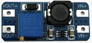
Pin Configuration and Descriptions
The ELC-X0122 has a simple pinout for easy integration into circuits. The table below describes each pin:
| Pin Name | Pin Number | Description |
|---|---|---|
| VIN | 1 | Input voltage pin (connect to the power source) |
| GND | 2 | Ground pin (common ground for input and output) |
| VOUT | 3 | Output voltage pin (connect to the load) |
| EN | 4 | Enable pin (logic HIGH to enable, LOW to disable) |
| FB | 5 | Feedback pin (used for output voltage regulation) |
Usage Instructions
How to Use the Component in a Circuit
- Connect the Input Voltage (VIN): Attach the positive terminal of your power source to the VIN pin and the negative terminal to the GND pin.
- Connect the Output Voltage (VOUT): Attach the load to the VOUT pin and ensure the load's ground is connected to the GND pin.
- Enable the Converter: Use the EN pin to enable or disable the converter. Connect it to a logic HIGH signal (e.g., 3.3V or 5V) to enable the converter.
- Set the Output Voltage: Use a resistor divider network connected to the FB pin to set the desired output voltage. Refer to the formula in the datasheet for precise calculations.
Important Considerations and Best Practices
- Input Voltage Range: Ensure the input voltage is within the specified range (2.5V to 12V). Exceeding this range may damage the component.
- Output Voltage Regulation: Use appropriate resistors for the feedback network to achieve the desired output voltage.
- Heat Dissipation: At high currents, the converter may generate heat. Use a heatsink or ensure proper ventilation to avoid overheating.
- Capacitor Selection: Use low-ESR capacitors for input and output filtering to minimize voltage ripple.
- Inductor Selection: Choose an inductor with the appropriate current rating and low resistance to optimize efficiency.
Example: Using the ELC-X0122 with an Arduino UNO
The ELC-X0122 can be used to power an Arduino UNO from a low-voltage source, such as a 3.7V Li-ion battery. Below is an example circuit and code to enable the converter and monitor its output voltage.
Circuit Diagram
- Connect the battery's positive terminal to the VIN pin and the negative terminal to the GND pin.
- Connect the VOUT pin to the Arduino's VIN pin.
- Use a digital pin on the Arduino to control the EN pin.
Arduino Code
// Define the pin connected to the EN pin of the Step-Up Converter
const int enablePin = 7;

void setup() {
  // Set the enable pin as an output
  pinMode(enablePin, OUTPUT);

  // Enable the Step-Up Converter
  digitalWrite(enablePin, HIGH);

  // Initialize serial communication for monitoring
  Serial.begin(9600);
}

void loop() {
  // Simulate monitoring the output voltage (example only)
  Serial.println("Step-Up Converter is enabled and powering the Arduino.");
  delay(1000); // Wait for 1 second
}
Troubleshooting and FAQs
Common Issues and Solutions
No Output Voltage:
- Ensure the EN pin is connected to a logic HIGH signal.
- Verify that the input voltage is within the specified range.
- Check for loose connections or damaged components.
Output Voltage is Incorrect:
- Verify the resistor values in the feedback network.
- Ensure the load does not exceed the maximum current rating (2A).
Excessive Heat Generation:
- Check for short circuits or excessive load current.
- Use a heatsink or improve ventilation around the converter.
High Voltage Ripple:
- Use low-ESR capacitors for input and output filtering.
- Ensure the inductor is properly rated for the application.
FAQs
Q: Can the ELC-X0122 be used with a 1.5V battery?
A: No, the minimum input voltage is 2.5V. Using a 1.5V battery will not power the converter.
Q: How do I calculate the feedback resistor values?
A: Refer to the formula in the datasheet:
( V_{OUT} = V_{REF} \times (1 + \frac{R1}{R2}) ),
where ( V_{REF} ) is the reference voltage (typically 1.25V).
Q: Is the ELC-X0122 suitable for powering LEDs?
A: Yes, it can be used to power LEDs, but ensure the output voltage and current are within the LED's specifications.
Q: Can I use the ELC-X0122 for audio applications?
A: Yes, but ensure proper filtering to minimize noise in sensitive audio circuits.