How to Use keypad 3x4: Examples, Pinouts, and Specs
Introduction
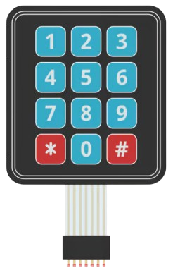
- The 3x4 matrix keypad is a compact input device consisting of 12 buttons arranged in 3 rows and 4 columns. Each button represents a unique combination of a row and a column, making it ideal for capturing user input in a variety of applications.
- Common applications include password entry systems, calculators, menu navigation interfaces, and embedded systems requiring numeric or alphanumeric input.
Explore Projects Built with keypad 3x4


Explore Projects Built with keypad 3x4
Technical Specifications
- Type: 3x4 Matrix Keypad
- Number of Buttons: 12 (3 rows × 4 columns)
- Operating Voltage: 3.3V to 5V
- Current Consumption: Typically < 10mA
- Button Layout: Numeric (0-9) and additional symbols (*, #)
- Interface: Digital (requires 7 GPIO pins for direct connection)
- Dimensions: Varies by manufacturer, typically compact and lightweight
- Material: Plastic or rubber buttons with a PCB or flexible membrane backing
Pin Configuration and Descriptions
The 3x4 keypad has 7 pins: 3 for rows and 4 for columns. The pinout may vary slightly depending on the manufacturer, so always refer to the specific datasheet for your keypad. Below is a general pin configuration:
| Pin | Name | Description |
|---|---|---|
| 1 | R1 | Row 1 (connect to GPIO pin) |
| 2 | R2 | Row 2 (connect to GPIO pin) |
| 3 | R3 | Row 3 (connect to GPIO pin) |
| 4 | C1 | Column 1 (connect to GPIO pin) |
| 5 | C2 | Column 2 (connect to GPIO pin) |
| 6 | C3 | Column 3 (connect to GPIO pin) |
| 7 | C4 | Column 4 (connect to GPIO pin) |
Usage Instructions
How to Use the Keypad in a Circuit
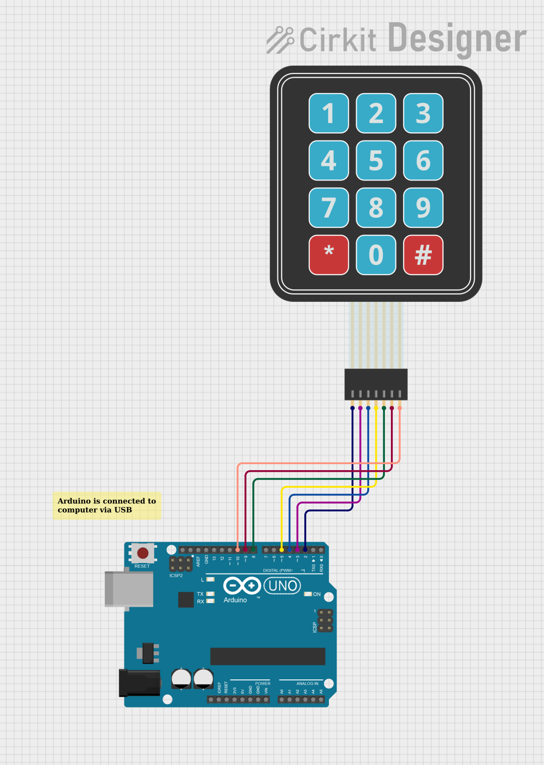
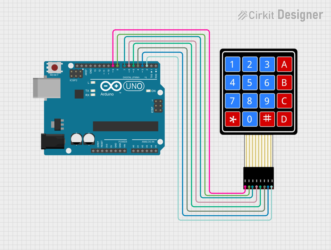
- Wiring: Connect the keypad's row and column pins to the GPIO pins of your microcontroller. For example:
- Rows (R1, R2, R3) → GPIO pins (e.g., D2, D3, D4 on Arduino UNO)
- Columns (C1, C2, C3, C4) → GPIO pins (e.g., D5, D6, D7, D8 on Arduino UNO)
- Pull-up Resistors: Use internal pull-up resistors on the microcontroller or external resistors to ensure stable readings.
- Library: Use a keypad library (e.g., Arduino Keypad Library) to simplify the process of detecting button presses.
Important Considerations and Best Practices
- Debouncing: Keypads may produce multiple signals for a single press due to mechanical bouncing. Use software debouncing techniques or libraries to handle this.
- Voltage Compatibility: Ensure the keypad's operating voltage matches your microcontroller's logic level (e.g., 5V for Arduino UNO).
- Pin Mapping: Verify the pin mapping of your specific keypad model to avoid incorrect connections.
- Durability: Avoid excessive force on the buttons to prolong the keypad's lifespan.
Example Code for Arduino UNO
Below is an example of how to use a 3x4 keypad with an Arduino UNO using the Keypad Library:
#include <Keypad.h>

// Define the rows and columns of the keypad
const byte ROWS = 3; // 3 rows
const byte COLS = 4; // 4 columns

// Define the keymap for the keypad
char keys[ROWS][COLS] = {
  {'1', '2', '3', 'A'},
  {'4', '5', '6', 'B'},
  {'7', '8', '9', 'C'},
  {'*', '0', '#', 'D'}
};

// Define the row and column pins connected to the Arduino
byte rowPins[ROWS] = {2, 3, 4};    // Connect to R1, R2, R3
byte colPins[COLS] = {5, 6, 7, 8}; // Connect to C1, C2, C3, C4

// Create a Keypad object
Keypad keypad = Keypad(makeKeymap(keys), rowPins, colPins, ROWS, COLS);

void setup() {
  Serial.begin(9600); // Initialize serial communication
  Serial.println("Keypad Test: Press a key");
}

void loop() {
  char key = keypad.getKey(); // Check if a key is pressed

  if (key) {
    // Print the pressed key to the Serial Monitor
    Serial.print("Key Pressed: ");
    Serial.println(key);
  }
}
Notes:
- Install the Keypad Library in the Arduino IDE via the Library Manager before uploading the code.
- Open the Serial Monitor (set to 9600 baud) to view the key presses.
Troubleshooting and FAQs
Common Issues
No Key Press Detected:
- Check the wiring between the keypad and the microcontroller.
- Ensure the correct pins are defined in the code.
- Verify that the keypad library is installed and included properly.
Incorrect Key Presses:
- Confirm the keymap matches the physical layout of your keypad.
- Check for loose or incorrect connections.
Multiple Key Presses Detected:
- Implement debouncing in software or use a library that handles it automatically.
Keypad Not Responding:
- Ensure the microcontroller's GPIO pins are configured as inputs.
- Verify the operating voltage of the keypad matches the microcontroller.
FAQs
Can I use fewer GPIO pins with a 3x4 keypad? Yes, you can use a multiplexer or shift register to reduce the number of GPIO pins required.
Is the keypad waterproof? Most 3x4 keypads are not waterproof. If needed, look for a sealed or membrane keypad.
Can I use this keypad with a Raspberry Pi? Yes, but you may need to use a Python library like
pad4pifor easier integration.How do I extend the keypad's cable length? Use shielded cables to reduce noise and interference over longer distances.