How to Use DIP Switch (8 Position): Examples, Pinouts, and Specs
Introduction
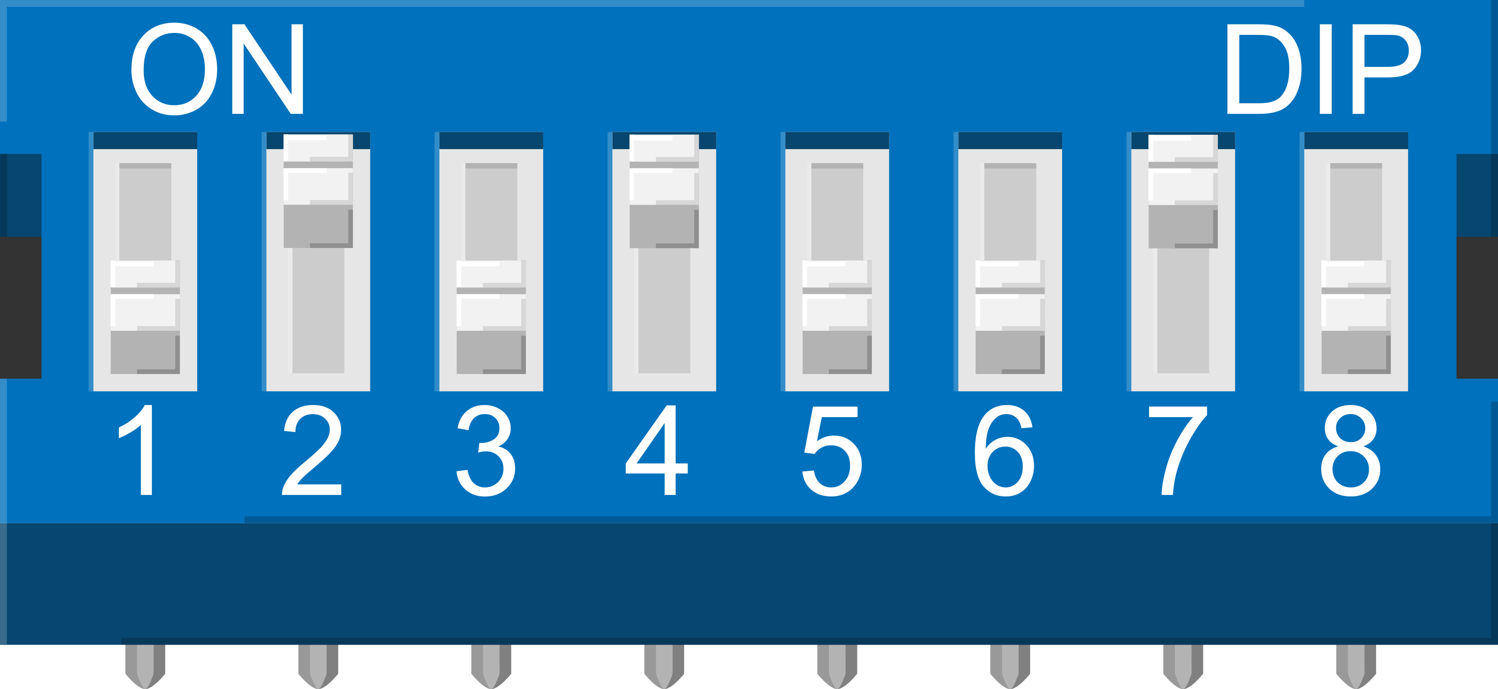
A DIP (Dual Inline Package) switch is a manual electric switch that is packaged in a standard dual in-line package. This particular DIP switch has 8 individual switch positions, allowing for a combination of settings to be selected. The 8 Position DIP Switch is commonly used to configure hardware settings, select options on a printed circuit board, or for prototyping work. It is a convenient way to make binary choices without the need for jumpers or soldering.
Explore Projects Built with DIP Switch (8 Position)
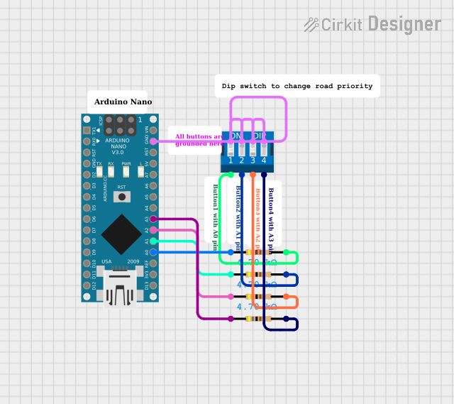
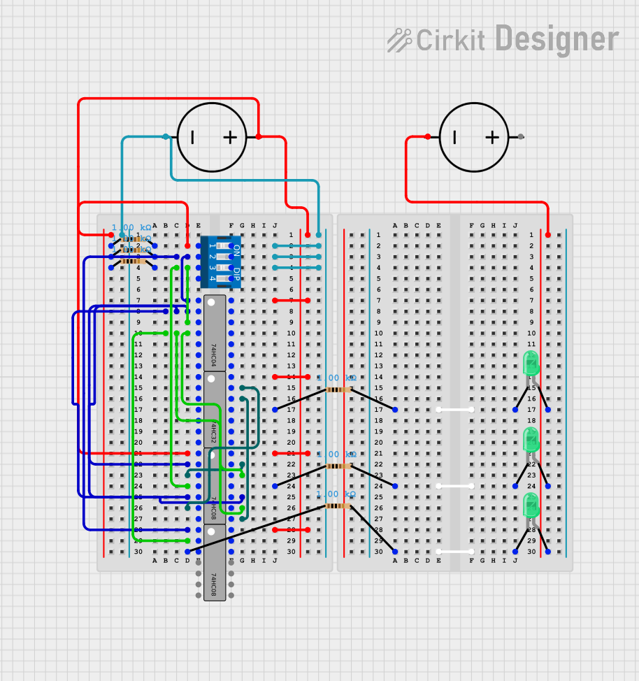

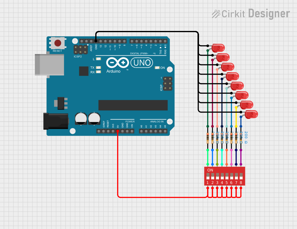
Explore Projects Built with DIP Switch (8 Position)
Common Applications and Use Cases
- Setting hardware configurations
- Selecting operating modes for electronic devices
- Adjusting parameters in electronic circuits
- Prototyping and development work
- User interface for setting preferences
Technical Specifications
Key Technical Details
- Switch Type: Single Pole Single Throw (SPST)
- Number of Positions: 8
- Contact Rating: Typically 25mA @ 24V DC
- Non-Switching Rating: 100mA @ 50V DC
- Contact Resistance: 50mΩ max
- Insulation Resistance: 100MΩ min at 500V DC
- Dielectric Strength: 500V AC for 1 minute
- Operating Temperature Range: -25°C to +70°C
Pin Configuration and Descriptions
| Pin Number | Description |
|---|---|
| 1 | Switch 1 |
| 2 | Switch 2 |
| 3 | Switch 3 |
| 4 | Switch 4 |
| 5 | Switch 5 |
| 6 | Switch 6 |
| 7 | Switch 7 |
| 8 | Switch 8 |
| 9 | Common (Ground) |
Each switch pin (1-8) corresponds to one of the 8 positions on the DIP switch. The common pin (9) is typically connected to ground.
Usage Instructions
How to Use the Component in a Circuit
- Mounting: Insert the DIP switch into the printed circuit board (PCB) and solder it in place, ensuring proper alignment of pins.
- Configuration: Use a small tool like a screwdriver to set each switch to the desired on (closed) or off (open) position.
- Connection: Connect the common pin to the ground of your circuit. Each switch pin can then be connected to the respective input or control pin on your device or microcontroller.
Important Considerations and Best Practices
- Debouncing: Although DIP switches do not typically require debouncing like mechanical buttons, ensure that the switch is set firmly to avoid intermittent connections.
- Handling: Avoid excessive force when changing switch positions to prevent damage.
- Soldering: Use proper soldering techniques to avoid cold joints or damage to the switch.
- Cleaning: Keep the DIP switch clean and free from dust, which can affect its performance.
Troubleshooting and FAQs
Common Issues Users Might Face
- Switch not responding: Ensure that the switch is properly soldered and that there is no debris obstructing the switch's movement.
- Intermittent connections: Check for loose connections or cold solder joints.
Solutions and Tips for Troubleshooting
- Resoldering: If a connection is not solid, reflow the solder on the pins of the DIP switch.
- Cleaning: Use compressed air or a soft brush to clean the DIP switch if debris is present.
FAQs
- Q: Can I use the DIP switch with higher voltages?
- A: No, you should adhere to the specified voltage ratings to prevent damage.
- Q: How do I know if the switch position is on or off?
- A: Typically, when the switch is pushed towards the numbered side, it is in the 'on' position, connecting the pin to the common ground.
Example Code for Arduino UNO
// Define the pin numbers connected to the DIP switch positions
const int dipPins[8] = {2, 3, 4, 5, 6, 7, 8, 9};

void setup() {
  // Initialize serial communication
  Serial.begin(9600);
  // Set all the DIP switch pins as inputs
  for (int i = 0; i < 8; i++) {
    pinMode(dipPins[i], INPUT_PULLUP);
    // Using the internal pull-up resistors
  }
}

void loop() {
  // Read the state of each switch position
  for (int i = 0; i < 8; i++) {
    int switchState = digitalRead(dipPins[i]);
    // Print the state of each switch
    Serial.print("Switch ");
    Serial.print(i + 1);
    Serial.print(": ");
    Serial.println(switchState == HIGH ? "OFF" : "ON");
    // When switch is ON, it connects the pin to GND (LOW)
  }
  // Add a delay before the next reading
  delay(1000);
}
This example code initializes an Arduino UNO to read the state of each switch in the 8 Position DIP Switch and prints the state to the Serial Monitor. Each switch is connected to a digital pin on the Arduino, and the common pin is connected to ground. The internal pull-up resistors are used to ensure a default HIGH state when the switch is open (off).