How to Use AC dimmer module: Examples, Pinouts, and Specs
Introduction
An AC dimmer module is a device used to control the brightness of an AC-powered light by adjusting the voltage and current flowing to the light fixture. It typically employs phase-cutting techniques, such as leading-edge or trailing-edge dimming, to regulate the power delivered to the load. These modules are widely used in home automation, lighting control systems, and industrial applications where precise control of light intensity is required.
Explore Projects Built with AC dimmer module

Explore Projects Built with AC dimmer module
Common Applications and Use Cases
- Dimming incandescent and halogen lamps
- Controlling the brightness of dimmable LED lights
- Home automation systems
- Stage lighting and theatrical effects
- Industrial lighting control
Technical Specifications
Below are the key technical details of a typical AC dimmer module:
| Parameter | Value |
|---|---|
| Input Voltage | 110V AC to 220V AC |
| Output Voltage | Adjustable (0V to input voltage) |
| Maximum Load Current | 2A to 5A (varies by model) |
| Control Voltage | 3.3V to 5V (logic level input) |
| Dimming Technique | Phase-cutting (leading or trailing edge) |
| Isolation | Optocoupler-based isolation |
| Operating Temperature | -20°C to 85°C |
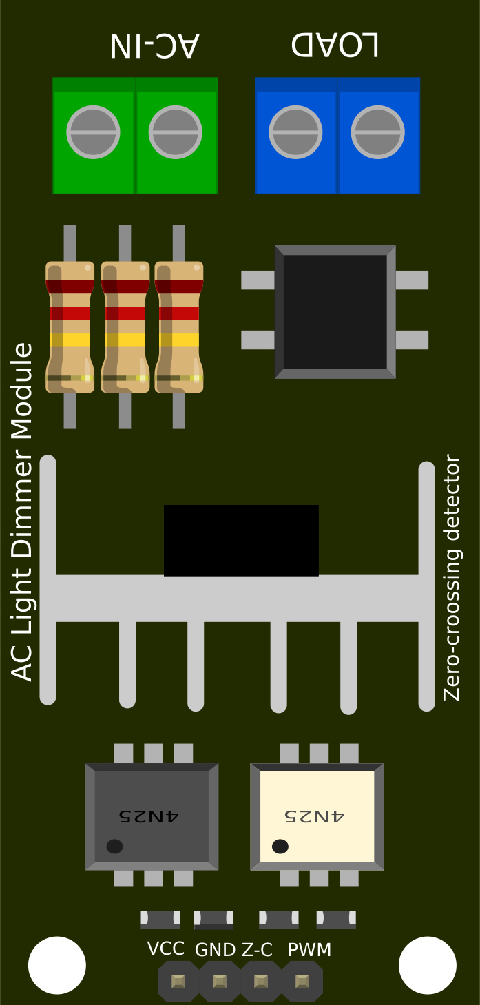
Pin Configuration and Descriptions
The AC dimmer module typically has the following pin configuration:
| Pin Name | Description |
|---|---|
| AC IN | Input terminals for AC mains voltage (110V-220V AC). |
| AC OUT | Output terminals for the dimmed AC voltage to the load (e.g., light bulb). |
| GND | Ground connection for the control circuit. |
| VCC | Power supply for the control circuit (typically 3.3V or 5V). |
| PWM/Signal | Control input pin for dimming (accepts PWM or logic HIGH/LOW signals). |
| ZC (optional) | Zero-crossing detection signal output (used for precise phase control). |
Usage Instructions
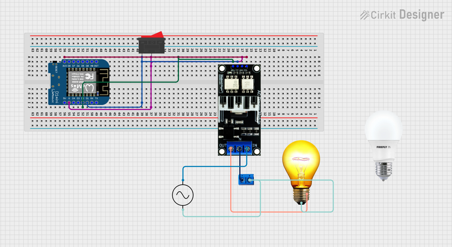
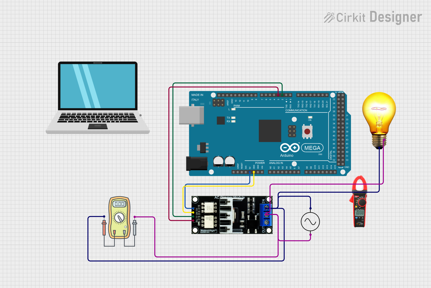
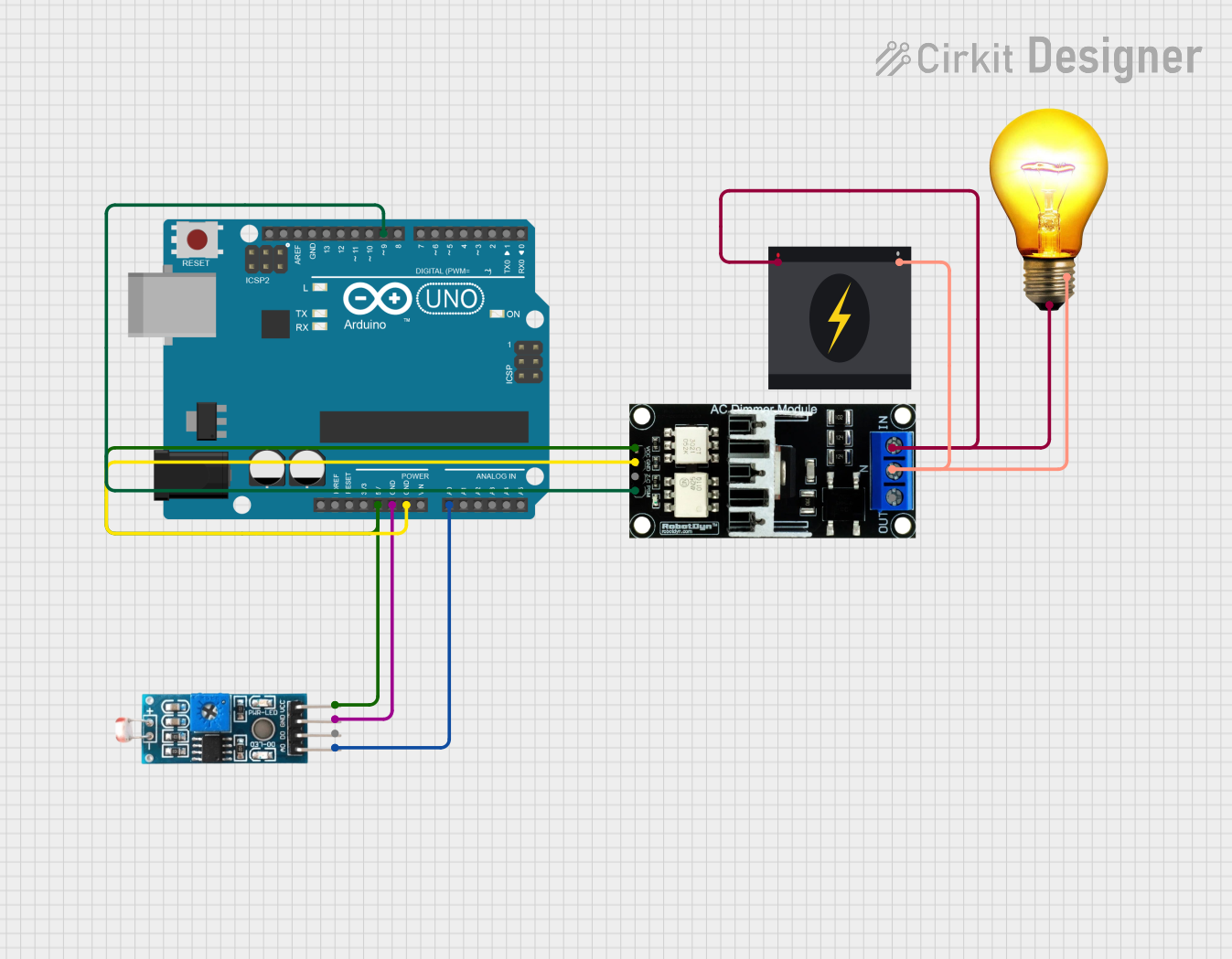
How to Use the AC Dimmer Module in a Circuit
Connect the AC Input and Output:
- Connect the AC mains voltage (110V-220V AC) to the
AC INterminals. - Connect the load (e.g., light bulb) to the
AC OUTterminals.
- Connect the AC mains voltage (110V-220V AC) to the
Power the Control Circuit:
- Provide a 3.3V or 5V DC power supply to the
VCCpin. - Connect the
GNDpin to the ground of your control circuit.
- Provide a 3.3V or 5V DC power supply to the
Control the Dimming:
- Use a microcontroller (e.g., Arduino UNO) to send a PWM signal to the
PWM/Signalpin. - The duty cycle of the PWM signal determines the brightness of the connected load.
- Use a microcontroller (e.g., Arduino UNO) to send a PWM signal to the
Optional Zero-Crossing Detection:
- If your module has a
ZCpin, connect it to a microcontroller input pin to synchronize the dimming with the AC mains zero-crossing point for smoother operation.
- If your module has a
Important Considerations and Best Practices
- Safety First: Always handle AC mains voltage with caution. Ensure proper insulation and avoid touching live wires.
- Load Compatibility: Verify that the connected load (e.g., light bulb) is dimmable and within the module's current rating.
- Heat Dissipation: The module may generate heat during operation. Use proper ventilation or a heatsink if necessary.
- PWM Frequency: Use a PWM frequency of 100Hz to 1kHz for optimal dimming performance.
- Isolation: Ensure that the control circuit is electrically isolated from the AC mains to prevent damage or hazards.
Example Code for Arduino UNO
Below is an example code to control an AC dimmer module using an Arduino UNO:
// Example code to control an AC dimmer module with Arduino UNO
// Connect the PWM/Signal pin of the dimmer module to Arduino pin 9

#define DIMMER_PIN 9  // PWM pin connected to the dimmer module

void setup() {
  pinMode(DIMMER_PIN, OUTPUT);  // Set the dimmer pin as an output
}

void loop() {
  // Gradually increase brightness
  for (int brightness = 0; brightness <= 255; brightness++) {
    analogWrite(DIMMER_PIN, brightness);  // Send PWM signal to dimmer
    delay(20);  // Small delay for smooth dimming
  }

  // Gradually decrease brightness
  for (int brightness = 255; brightness >= 0; brightness--) {
    analogWrite(DIMMER_PIN, brightness);  // Send PWM signal to dimmer
    delay(20);  // Small delay for smooth dimming
  }
}
Troubleshooting and FAQs
Common Issues and Solutions
The light does not turn on:
- Ensure the AC mains voltage is properly connected to the
AC INterminals. - Verify that the load is connected to the
AC OUTterminals. - Check the control circuit power supply (
VCCandGND).
- Ensure the AC mains voltage is properly connected to the
Flickering light:
- Ensure the load is compatible with dimming (e.g., dimmable LED or incandescent bulb).
- Adjust the PWM frequency to reduce flickering (try 100Hz to 1kHz).
- Verify that the zero-crossing detection is functioning correctly.
Overheating module:
- Check that the load current does not exceed the module's maximum rating.
- Improve ventilation or add a heatsink to dissipate heat.
No response to PWM signal:
- Verify the connection between the microcontroller and the
PWM/Signalpin. - Ensure the PWM signal voltage matches the module's control voltage (3.3V or 5V).
- Verify the connection between the microcontroller and the
FAQs
Q: Can I use the AC dimmer module with non-dimmable LED lights?
A: No, non-dimmable LED lights are not compatible with dimming and may flicker or get damaged.
Q: What happens if I exceed the module's current rating?
A: Exceeding the current rating can cause the module to overheat, fail, or even pose a fire hazard. Always stay within the specified limits.
Q: Can I control multiple lights with one dimmer module?
A: Yes, as long as the total current of all connected lights does not exceed the module's maximum load current.
Q: Is it safe to use the module without isolation?
A: No, always ensure proper electrical isolation between the control circuit and the AC mains to prevent hazards.