Cirkit Designer Logo
Cirkit Designer
Your all-in-one circuit design IDE
Home / 
Component Documentation

How to Use HOMELYLIFE Buck Converter Step Down DC 12V/24V to 5V 20A 100W: Examples, Pinouts, and Specs

Image of HOMELYLIFE Buck Converter Step Down DC 12V/24V to 5V 20A 100W
Cirkit Designer LogoDesign with HOMELYLIFE Buck Converter Step Down DC 12V/24V to 5V 20A 100W in Cirkit Designer

Introduction

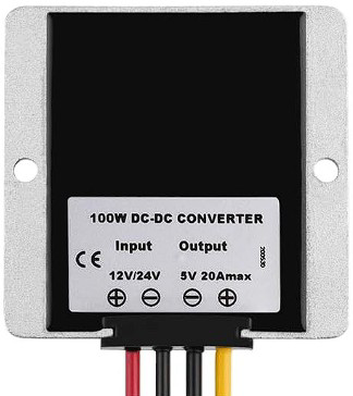
The HOMELYLIFE Buck Converter, manufactured by EPBOWPT (Part ID: 12V/24V-5V 10A), is a high-performance DC-DC step-down voltage regulator. It efficiently converts input voltages of 12V or 24V to a stable 5V output, delivering up to 20A of current and 100W of power. This makes it ideal for powering low-voltage devices such as USB-powered electronics, microcontrollers, LED strips, and other 5V systems.

Explore Projects Built with HOMELYLIFE Buck Converter Step Down DC 12V/24V to 5V 20A 100W

Use Cirkit Designer to design, explore, and prototype these projects online. Some projects support real-time simulation. Click "Open Project" to start designing instantly!
Battery-Powered UPS with Step-Down Buck Converter and BMS
Image of Mini ups: A project utilizing HOMELYLIFE Buck Converter Step Down DC 12V/24V to 5V 20A 100W in a practical application
This circuit is a power management system that steps down a 240V AC input to a lower DC voltage using a buck converter, which then powers a 40W UPS. The UPS is controlled by a rocker switch and is backed up by a battery management system (BMS) connected to three 3.7V batteries in series, ensuring continuous power supply.
Cirkit Designer LogoOpen Project in Cirkit Designer
USB Power Supply with Overcurrent Protection
Image of USB Charging port: A project utilizing HOMELYLIFE Buck Converter Step Down DC 12V/24V to 5V 20A 100W in a practical application
This circuit is designed to step down voltage from a 12V battery to a lower voltage suitable for USB devices. It includes a buck converter connected to the battery through a fuse and fuse holder for overcurrent protection. The output of the buck converter is connected to a USB female port, providing a regulated power supply for USB-powered devices.
Cirkit Designer LogoOpen Project in Cirkit Designer
Battery-Powered DC Generator with XL4015 Buck Converter
Image of conveyor: A project utilizing HOMELYLIFE Buck Converter Step Down DC 12V/24V to 5V 20A 100W in a practical application
This circuit consists of a 12V battery connected to a rocker switch, which controls the input to an XL4015 DC Buck Step-down converter. The converter steps down the voltage to power a DC generator, with the generator's output connected back to the converter to form a feedback loop.
Cirkit Designer LogoOpen Project in Cirkit Designer
Dual Motor Control Circuit with Directional Switching and Voltage Regulation
Image of Pencuci Kipas: A project utilizing HOMELYLIFE Buck Converter Step Down DC 12V/24V to 5V 20A 100W in a practical application
This circuit features a 12V battery connected through a rocker switch to two buck converters, one of which steps down the voltage to power two DC mini metal gear motors, and the other is connected to a directional switch that controls a third DC mini metal gear motor. The XL4015 5A DC Buck Step-down converter's output is connected to two motors, allowing them to run at a reduced voltage, while the other buck converter's output is routed through a directional switch to control the direction of the third motor.
Cirkit Designer LogoOpen Project in Cirkit Designer

Explore Projects Built with HOMELYLIFE Buck Converter Step Down DC 12V/24V to 5V 20A 100W

Use Cirkit Designer to design, explore, and prototype these projects online. Some projects support real-time simulation. Click "Open Project" to start designing instantly!
Image of Mini ups: A project utilizing HOMELYLIFE Buck Converter Step Down DC 12V/24V to 5V 20A 100W in a practical application
Battery-Powered UPS with Step-Down Buck Converter and BMS
This circuit is a power management system that steps down a 240V AC input to a lower DC voltage using a buck converter, which then powers a 40W UPS. The UPS is controlled by a rocker switch and is backed up by a battery management system (BMS) connected to three 3.7V batteries in series, ensuring continuous power supply.
Cirkit Designer LogoOpen Project in Cirkit Designer
Image of USB Charging port: A project utilizing HOMELYLIFE Buck Converter Step Down DC 12V/24V to 5V 20A 100W in a practical application
USB Power Supply with Overcurrent Protection
This circuit is designed to step down voltage from a 12V battery to a lower voltage suitable for USB devices. It includes a buck converter connected to the battery through a fuse and fuse holder for overcurrent protection. The output of the buck converter is connected to a USB female port, providing a regulated power supply for USB-powered devices.
Cirkit Designer LogoOpen Project in Cirkit Designer
Image of conveyor: A project utilizing HOMELYLIFE Buck Converter Step Down DC 12V/24V to 5V 20A 100W in a practical application
Battery-Powered DC Generator with XL4015 Buck Converter
This circuit consists of a 12V battery connected to a rocker switch, which controls the input to an XL4015 DC Buck Step-down converter. The converter steps down the voltage to power a DC generator, with the generator's output connected back to the converter to form a feedback loop.
Cirkit Designer LogoOpen Project in Cirkit Designer
Image of Pencuci Kipas: A project utilizing HOMELYLIFE Buck Converter Step Down DC 12V/24V to 5V 20A 100W in a practical application
Dual Motor Control Circuit with Directional Switching and Voltage Regulation
This circuit features a 12V battery connected through a rocker switch to two buck converters, one of which steps down the voltage to power two DC mini metal gear motors, and the other is connected to a directional switch that controls a third DC mini metal gear motor. The XL4015 5A DC Buck Step-down converter's output is connected to two motors, allowing them to run at a reduced voltage, while the other buck converter's output is routed through a directional switch to control the direction of the third motor.
Cirkit Designer LogoOpen Project in Cirkit Designer

Common Applications and Use Cases

  • Powering USB devices (e.g., smartphones, tablets, Raspberry Pi)
  • Supplying power to 5V microcontrollers (e.g., Arduino, ESP32)
  • Driving 5V LED strips or lighting systems
  • Automotive applications for powering 5V accessories
  • Industrial equipment requiring a stable 5V power source

Technical Specifications

Key Technical Details

Parameter Value
Input Voltage Range 8V to 40V
Output Voltage 5V (fixed)
Maximum Output Current 20A
Maximum Output Power 100W
Efficiency Up to 95%
Operating Temperature -40°C to +85°C
Dimensions 74mm x 74mm x 32mm
Weight ~150g
Protection Features Overcurrent, Overvoltage,
Overtemperature, Short Circuit

Pin Configuration and Descriptions

Pin Name Description
VIN+ Positive input voltage terminal (8V-40V)
VIN- Negative input voltage terminal (GND)
VOUT+ Positive output voltage terminal (5V)
VOUT- Negative output voltage terminal (GND)

Usage Instructions

How to Use the Component in a Circuit

  1. Connect the Input Voltage:
    • Attach the VIN+ terminal to the positive terminal of your power source (12V or 24V).
    • Connect the VIN- terminal to the ground (GND) of your power source.
  2. Connect the Output Voltage:
    • Attach the VOUT+ terminal to the positive terminal of your load (e.g., a 5V device).
    • Connect the VOUT- terminal to the ground (GND) of your load.
  3. Verify Connections:
    • Double-check all connections to ensure proper polarity and secure wiring.
  4. Power On:
    • Turn on the power source. The buck converter will step down the input voltage to a stable 5V output.

Important Considerations and Best Practices

  • Heat Dissipation: The converter may generate heat under high loads. Ensure adequate ventilation or use a heatsink if necessary.
  • Input Voltage Range: Do not exceed the input voltage range (8V-40V) to avoid damaging the component.
  • Load Current: Ensure the connected load does not exceed the maximum output current of 20A.
  • Wiring: Use thick wires for high-current applications to minimize voltage drops and overheating.
  • Polarity: Always connect the terminals with the correct polarity to prevent damage.

Example: Using with an Arduino UNO

The HOMELYLIFE Buck Converter can be used to power an Arduino UNO by stepping down a 12V or 24V input to 5V. Below is an example circuit and Arduino code to blink an LED:

Circuit Connections

  1. Connect the VIN+ and VIN- terminals of the buck converter to a 12V power source.
  2. Connect the VOUT+ terminal to the 5V pin of the Arduino UNO.
  3. Connect the VOUT- terminal to the GND pin of the Arduino UNO.
  4. Connect an LED to pin 13 of the Arduino UNO with a 220-ohm resistor in series.

Arduino Code

// Simple LED Blink Example
// This code blinks an LED connected to pin 13 of the Arduino UNO

void setup() {
  pinMode(13, OUTPUT); // Set pin 13 as an output
}

void loop() {
  digitalWrite(13, HIGH); // Turn the LED on
  delay(1000);            // Wait for 1 second
  digitalWrite(13, LOW);  // Turn the LED off
  delay(1000);            // Wait for 1 second
}

Troubleshooting and FAQs

Common Issues and Solutions

  1. No Output Voltage:

    • Cause: Incorrect wiring or insufficient input voltage.
    • Solution: Verify all connections and ensure the input voltage is within the 8V-40V range.
  2. Overheating:

    • Cause: High load current or poor ventilation.
    • Solution: Reduce the load current or improve heat dissipation with a heatsink or fan.
  3. Output Voltage Fluctuations:

    • Cause: Unstable input voltage or excessive load.
    • Solution: Use a stable power source and ensure the load does not exceed 20A.
  4. Short Circuit Protection Triggered:

    • Cause: Output terminals are shorted.
    • Solution: Disconnect the power source, fix the short circuit, and reconnect.

FAQs

Q: Can this converter be used with a 24V battery system?
A: Yes, the converter supports input voltages up to 40V, making it compatible with 24V battery systems.

Q: Is the output voltage adjustable?
A: No, the output voltage is fixed at 5V.

Q: Can I use this converter to power multiple devices?
A: Yes, as long as the total current draw does not exceed 20A.

Q: Does the converter have reverse polarity protection?
A: No, ensure correct polarity when connecting the input and output terminals to avoid damage.