Cirkit Designer Logo
Cirkit Designer
Your all-in-one circuit design IDE
Home / 
Component Documentation

How to Use Módulo 03962A Cargador de batería: Examples, Pinouts, and Specs

Image of Módulo 03962A Cargador de batería
Cirkit Designer LogoDesign with Módulo 03962A Cargador de batería in Cirkit Designer

Introduction

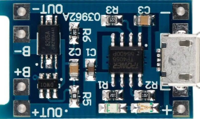
The Módulo 03962A Cargador de batería is a versatile and efficient battery charger module designed to support a wide range of battery types, including lithium-ion, lead-acid, and other rechargeable batteries. It features built-in overcharge protection, adjustable charging parameters, and a compact design, making it ideal for DIY electronics projects, battery-powered devices, and energy storage systems.

Explore Projects Built with Módulo 03962A Cargador de batería

Use Cirkit Designer to design, explore, and prototype these projects online. Some projects support real-time simulation. Click "Open Project" to start designing instantly!
18650 Li-ion Battery Pack with 4S40A BMS and XL4016 Voltage Regulator for Battery-Powered Applications
Image of Power Bank: A project utilizing Módulo 03962A Cargador de batería in a practical application
This circuit is a battery management and charging system for a 4S Li-ion battery pack. It includes multiple 18650 Li-ion batteries connected to a 4S40A BMS for balancing and protection, a battery indicator for monitoring charge status, and an XL4016 module for voltage regulation. The system is designed to be charged via a 20V input from a charger.
Cirkit Designer LogoOpen Project in Cirkit Designer
12V Power Supply with HX-M350 Backup Battery Switching
Image of power : A project utilizing Módulo 03962A Cargador de batería in a practical application
This circuit is designed to provide a backup power solution using a 12V 200Ah battery and a 12V power supply, with the HX-M350 module managing the switching between these power sources. The HX-M350 module automatically switches to the battery power when the main 12V power supply fails or is unavailable, ensuring uninterrupted power to the load. There is no microcontroller or additional control logic involved, indicating that the switching mechanism is likely handled entirely by the HX-M350 module itself.
Cirkit Designer LogoOpen Project in Cirkit Designer
Battery-Powered 18650 Li-ion Charger with USB Output and Adjustable Voltage Regulator
Image of Breadboard: A project utilizing Módulo 03962A Cargador de batería in a practical application
This circuit is a battery management and power supply system that uses three 3.7V batteries connected to a 3S 10A Li-ion 18650 Charger Protection Board Module for balanced charging and protection. The system includes a TP4056 Battery Charging Protection Module for additional charging safety, a Step Up Boost Power Converter to regulate and boost the voltage, and a USB regulator to provide a stable 5V output, controlled by a push switch.
Cirkit Designer LogoOpen Project in Cirkit Designer
Solar-Powered Battery Charging and Monitoring System with TP4056 and 7-Segment Voltmeter
Image of CKT: A project utilizing Módulo 03962A Cargador de batería in a practical application
This circuit is a solar-powered battery charging and monitoring system. It uses a TP4056 module to charge a Li-ion 18650 battery from solar cells and a DC generator, with multiple LEDs and a voltmeter to indicate the charging status and battery voltage. The circuit also includes transistors and resistors to control the LEDs and a bridge rectifier for AC to DC conversion.
Cirkit Designer LogoOpen Project in Cirkit Designer

Explore Projects Built with Módulo 03962A Cargador de batería

Use Cirkit Designer to design, explore, and prototype these projects online. Some projects support real-time simulation. Click "Open Project" to start designing instantly!
Image of Power Bank: A project utilizing Módulo 03962A Cargador de batería in a practical application
18650 Li-ion Battery Pack with 4S40A BMS and XL4016 Voltage Regulator for Battery-Powered Applications
This circuit is a battery management and charging system for a 4S Li-ion battery pack. It includes multiple 18650 Li-ion batteries connected to a 4S40A BMS for balancing and protection, a battery indicator for monitoring charge status, and an XL4016 module for voltage regulation. The system is designed to be charged via a 20V input from a charger.
Cirkit Designer LogoOpen Project in Cirkit Designer
Image of power : A project utilizing Módulo 03962A Cargador de batería in a practical application
12V Power Supply with HX-M350 Backup Battery Switching
This circuit is designed to provide a backup power solution using a 12V 200Ah battery and a 12V power supply, with the HX-M350 module managing the switching between these power sources. The HX-M350 module automatically switches to the battery power when the main 12V power supply fails or is unavailable, ensuring uninterrupted power to the load. There is no microcontroller or additional control logic involved, indicating that the switching mechanism is likely handled entirely by the HX-M350 module itself.
Cirkit Designer LogoOpen Project in Cirkit Designer
Image of Breadboard: A project utilizing Módulo 03962A Cargador de batería in a practical application
Battery-Powered 18650 Li-ion Charger with USB Output and Adjustable Voltage Regulator
This circuit is a battery management and power supply system that uses three 3.7V batteries connected to a 3S 10A Li-ion 18650 Charger Protection Board Module for balanced charging and protection. The system includes a TP4056 Battery Charging Protection Module for additional charging safety, a Step Up Boost Power Converter to regulate and boost the voltage, and a USB regulator to provide a stable 5V output, controlled by a push switch.
Cirkit Designer LogoOpen Project in Cirkit Designer
Image of CKT: A project utilizing Módulo 03962A Cargador de batería in a practical application
Solar-Powered Battery Charging and Monitoring System with TP4056 and 7-Segment Voltmeter
This circuit is a solar-powered battery charging and monitoring system. It uses a TP4056 module to charge a Li-ion 18650 battery from solar cells and a DC generator, with multiple LEDs and a voltmeter to indicate the charging status and battery voltage. The circuit also includes transistors and resistors to control the LEDs and a bridge rectifier for AC to DC conversion.
Cirkit Designer LogoOpen Project in Cirkit Designer

Common Applications and Use Cases

  • Charging lithium-ion or lead-acid batteries in DIY projects
  • Powering portable electronics and battery-operated devices
  • Energy storage systems for solar panels or renewable energy setups
  • Battery maintenance and testing in laboratories or workshops

Technical Specifications

The following table outlines the key technical details of the Módulo 03962A Cargador de batería:

Parameter Value
Input Voltage Range 5V to 20V DC
Output Voltage Range Adjustable (4.2V, 8.4V, 12.6V, etc.)
Maximum Charging Current 2A
Efficiency Up to 92%
Protection Features Overcharge, short-circuit, and reverse polarity
Dimensions 25mm x 20mm x 10mm
Operating Temperature -20°C to 60°C

Pin Configuration and Descriptions

The Módulo 03962A has the following pinout:

Pin Name Description
VIN+ Positive input voltage terminal (5V to 20V DC)
VIN- Negative input voltage terminal (ground)
BAT+ Positive terminal for connecting the battery
BAT- Negative terminal for connecting the battery
ADJ Adjustment pin for setting the output voltage
LED1 Charging status indicator (e.g., red for charging)
LED2 Fully charged indicator (e.g., green for fully charged)

Usage Instructions

How to Use the Component in a Circuit

  1. Connect the Input Voltage:

    • Connect a DC power source (5V to 20V) to the VIN+ and VIN- pins.
    • Ensure the input voltage matches the requirements of the battery being charged.
  2. Connect the Battery:

    • Attach the battery's positive terminal to the BAT+ pin and the negative terminal to the BAT- pin.
    • Double-check the polarity to avoid damage to the module or battery.
  3. Adjust the Output Voltage:

    • Use the ADJ pin or onboard potentiometer (if available) to set the desired charging voltage.
    • Refer to the battery's datasheet for the correct charging voltage.
  4. Monitor Charging Status:

    • Observe the LED1 and LED2 indicators for charging progress:
      • LED1 (red): Charging in progress.
      • LED2 (green): Charging complete.

Important Considerations and Best Practices

  • Verify Battery Specifications: Ensure the battery's voltage and current ratings are compatible with the module.
  • Heat Dissipation: If charging at high currents, ensure proper ventilation or add a heatsink to prevent overheating.
  • Avoid Overdischarge: Do not connect deeply discharged batteries, as this may damage the module or the battery.
  • Safety First: Always handle batteries with care to avoid short circuits, overheating, or fire hazards.

Example: Using with an Arduino UNO

The Módulo 03962A can be used in conjunction with an Arduino UNO to monitor the charging process. Below is an example code snippet to read the charging status using the Arduino's digital pins:

// Define pins for the charging status LEDs
const int chargingPin = 2;  // Connect LED1 (charging indicator) to pin 2
const int chargedPin = 3;   // Connect LED2 (charged indicator) to pin 3

void setup() {
  // Initialize serial communication for debugging
  Serial.begin(9600);

  // Set the LED pins as input
  pinMode(chargingPin, INPUT);
  pinMode(chargedPin, INPUT);
}

void loop() {
  // Read the status of the charging and charged LEDs
  int chargingStatus = digitalRead(chargingPin);
  int chargedStatus = digitalRead(chargedPin);

  // Print the charging status to the Serial Monitor
  if (chargingStatus == HIGH) {
    Serial.println("Battery is charging...");
  } else if (chargedStatus == HIGH) {
    Serial.println("Battery is fully charged!");
  } else {
    Serial.println("No battery detected or idle state.");
  }

  // Add a small delay to avoid flooding the Serial Monitor
  delay(1000);
}

Troubleshooting and FAQs

Common Issues and Solutions

  1. Module Not Powering On:

    • Cause: Incorrect input voltage or loose connections.
    • Solution: Verify the input voltage is within the 5V to 20V range and check all connections.
  2. Battery Not Charging:

    • Cause: Incorrect polarity or incompatible battery type.
    • Solution: Double-check the battery's polarity and ensure it matches the module's specifications.
  3. Overheating During Operation:

    • Cause: High charging current or poor ventilation.
    • Solution: Reduce the charging current or improve heat dissipation with a heatsink or fan.
  4. LED Indicators Not Working:

    • Cause: Faulty LEDs or incorrect wiring.
    • Solution: Test the LEDs with a multimeter and verify the connections.

FAQs

Q1: Can this module charge multiple batteries in series?
A1: Yes, but ensure the total voltage of the series-connected batteries matches the module's output voltage.

Q2: Is it safe to leave the battery connected after it is fully charged?
A2: Yes, the module includes overcharge protection to prevent damage to the battery.

Q3: Can I use this module with a solar panel?
A3: Yes, as long as the solar panel's output voltage and current are within the module's input range.

Q4: How do I adjust the charging current?
A4: The charging current is typically fixed, but some versions of the module may allow adjustment via a resistor or potentiometer. Check the module's datasheet for details.