How to Use 3S BMS Charging 12v Multicharger quick charging Boost Charger: Examples, Pinouts, and Specs
Introduction
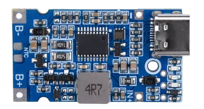
The 3S BMS Charging 12V Multicharger Quick Charging Boost Charger by ALI is a versatile and efficient battery management system (BMS) designed for charging 3-cell (3S) lithium-ion or lithium-polymer battery packs. This component integrates overcharge, over-discharge, and overcurrent protection, ensuring the safety and longevity of your battery packs. It also features a boost charging capability, enabling faster and more efficient charging.
Explore Projects Built with 3S BMS Charging 12v Multicharger quick charging Boost Charger


Explore Projects Built with 3S BMS Charging 12v Multicharger quick charging Boost Charger
Common Applications and Use Cases
- Charging 3S lithium-ion or lithium-polymer battery packs in portable devices
- Power banks and backup power systems
- DIY electronics projects requiring 12V battery management
- Robotics and remote-controlled devices
- Solar-powered battery charging systems
Technical Specifications
Below are the key technical details and pin configuration for the 3S BMS Charging 12V Multicharger Quick Charging Boost Charger:
Key Technical Details
| Parameter | Value |
|---|---|
| Input Voltage Range | 12V to 24V |
| Output Voltage | 12.6V (for 3S battery packs) |
| Maximum Charging Current | 3A |
| Overcharge Protection | 4.25V ± 0.05V per cell |
| Over-discharge Protection | 2.8V ± 0.05V per cell |
| Overcurrent Protection | 6A |
| Efficiency | Up to 95% |
| Operating Temperature | -20°C to 60°C |
| Dimensions | 50mm x 20mm x 10mm |
Pin Configuration and Descriptions
| Pin Name | Description |
|---|---|
| B+ | Positive terminal of the battery pack |
| B- | Negative terminal of the battery pack |
| P+ | Positive terminal of the load or charging input |
| P- | Negative terminal of the load or charging input |
| C+ | Positive terminal for the charging input (if separate from P+) |
| C- | Negative terminal for the charging input (if separate from P-) |
Usage Instructions
How to Use the Component in a Circuit
Connect the Battery Pack:
- Connect the positive terminal of the 3S battery pack to the B+ pin.
- Connect the negative terminal of the battery pack to the B- pin.
Connect the Load:
- Connect the positive terminal of the load to the P+ pin.
- Connect the negative terminal of the load to the P- pin.
Connect the Charger:
- If the charger shares the same terminals as the load, connect the charger to P+ and P-.
- If the charger has separate terminals, connect the positive terminal to C+ and the negative terminal to C-.
Power On:
- Ensure the input voltage is within the specified range (12V to 24V).
- Turn on the charger and monitor the charging process.
Important Considerations and Best Practices
- Battery Compatibility: Ensure the battery pack is a 3S lithium-ion or lithium-polymer type. Using incompatible batteries may damage the BMS or the batteries.
- Heat Dissipation: The BMS may generate heat during operation. Ensure proper ventilation or use a heatsink if necessary.
- Avoid Overloading: Do not exceed the maximum charging current (3A) or overcurrent protection limit (6A).
- Polarity Check: Double-check all connections to avoid reverse polarity, which can damage the BMS.
Arduino UNO Example Code
If you are using this BMS with an Arduino UNO to monitor battery voltage, you can use the following code:
// Example code to monitor 3S battery voltage using Arduino UNO
// Connect the battery's positive terminal to an analog pin via a voltage divider

const int voltagePin = A0; // Analog pin connected to the voltage divider
const float voltageDividerRatio = 5.7; // Adjust based on your resistor values
const float referenceVoltage = 5.0; // Arduino UNO reference voltage (5V)

void setup() {
  Serial.begin(9600); // Initialize serial communication
}

void loop() {
  int analogValue = analogRead(voltagePin); // Read the analog pin value
  float batteryVoltage = (analogValue / 1023.0) * referenceVoltage * voltageDividerRatio;

  // Print the battery voltage to the Serial Monitor
  Serial.print("Battery Voltage: ");
  Serial.print(batteryVoltage);
  Serial.println(" V");

  delay(1000); // Wait for 1 second before the next reading
}
Note: Use a voltage divider to scale down the battery voltage to a safe range for the Arduino's analog input (0-5V). Choose resistor values carefully to match the voltage divider ratio.
Troubleshooting and FAQs
Common Issues and Solutions
BMS Not Charging the Battery:
- Cause: Incorrect wiring or insufficient input voltage.
- Solution: Verify all connections and ensure the input voltage is within the specified range (12V to 24V).
Overheating During Operation:
- Cause: High current draw or poor ventilation.
- Solution: Reduce the load current and ensure proper heat dissipation.
Battery Not Reaching Full Charge:
- Cause: Faulty battery or incorrect overcharge protection settings.
- Solution: Check the battery health and ensure the BMS is configured for 3S batteries.
Load Not Powering On:
- Cause: Over-discharge protection triggered.
- Solution: Recharge the battery to reset the over-discharge protection.
FAQs
Can I use this BMS for a 4S battery pack?
No, this BMS is specifically designed for 3S battery packs. Using it with a 4S pack may result in improper charging and damage.What happens if I exceed the maximum charging current?
The BMS will activate overcurrent protection, cutting off the charging process to prevent damage.Can I use this BMS with a solar panel?
Yes, as long as the solar panel's output voltage and current are within the specified range (12V to 24V, max 3A).Is this BMS waterproof?
No, this BMS is not waterproof. Avoid exposing it to moisture or water.
By following this documentation, you can safely and effectively use the 3S BMS Charging 12V Multicharger Quick Charging Boost Charger in your projects.