How to Use ESP32 Devkit V1: Examples, Pinouts, and Specs
Introduction
The ESP32 Devkit V1 is a versatile and powerful microcontroller development board that harnesses the capabilities of the ESP32 chipset. This board is widely used in the Internet of Things (IoT) projects due to its integrated Wi-Fi and Bluetooth functionalities. It is suitable for a variety of applications, including smart home devices, wireless sensors, and robotics.
Explore Projects Built with ESP32 Devkit V1


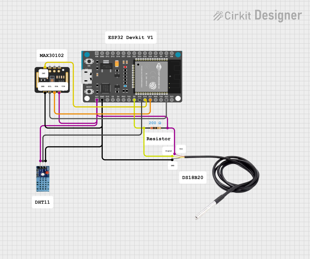
Explore Projects Built with ESP32 Devkit V1
Common Applications and Use Cases
- Smart Home Automation
- IoT Sensor Nodes
- Wearable Electronics
- Wireless Control Systems
Technical Specifications
Key Technical Details
- Microcontroller: ESP32
- Operating Voltage: 3.3V
- Input Voltage: 7-12V
- Digital I/O Pins: 25
- Analog Input Pins: 12 (ADC)
- Flash Memory: 4MB
- SRAM: 520 KB
- Clock Speed: 240MHz
- Wi-Fi: 802.11 b/g/n
- Bluetooth: v4.2 BR/EDR and BLE
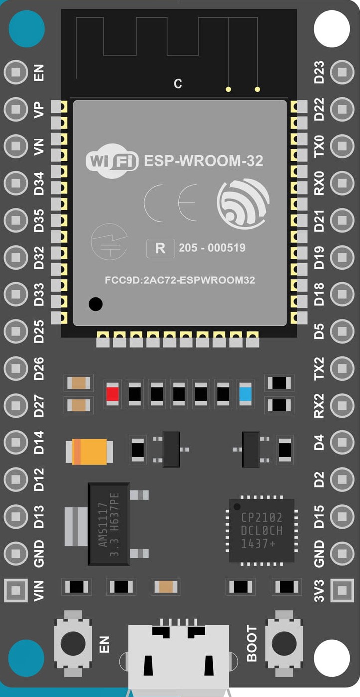
Pin Configuration and Descriptions
| Pin Number | Function | Description |
|---|---|---|
| 1 | 3V3 | 3.3V power supply |
| 2 | GND | Ground |
| 3 | EN | Reset pin (active low) |
| 4 | VP | GPIO36, ADC1_CH0, Sensor VP |
| 5 | VN | GPIO39, ADC1_CH3, Sensor VN |
| ... | ... | ... |
| 36 | IO23 | GPIO23, VSPI MOSI |
| 37 | IO22 | GPIO22, I2C SCL, VSPI CLK |
| 38 | TXD0 | GPIO1, U0TXD, Serial1 TX |
| 39 | RXD0 | GPIO3, U0RXD, Serial1 RX |
| ... | ... | ... |
Note: This table is not exhaustive and only includes a selection of pins.
Usage Instructions
How to Use the Component in a Circuit
Powering the ESP32 Devkit V1:
- Connect a power supply to the VIN pin for 7-12V input or use the micro USB port for 5V input.
Establishing a Serial Connection:
- Connect the TX and RX pins to a USB-to-serial converter to communicate with a PC.
Programming the ESP32:
- Use the micro USB port to connect the ESP32 Devkit V1 to a computer.
- Select the appropriate board and port in your IDE (e.g., Arduino IDE).
Connecting to Wi-Fi:
- Utilize the onboard Wi-Fi capabilities to connect to a network for IoT applications.
Using Bluetooth:
- Implement Bluetooth communication using the board's Bluetooth functionality.
Important Considerations and Best Practices
- Ensure that the input voltage does not exceed the recommended range to prevent damage.
- Use a stable power supply to avoid unexpected resets during Wi-Fi and Bluetooth operations.
- When using Wi-Fi and Bluetooth, consider the power consumption and plan your power management strategy accordingly.
- Be cautious with the GPIO pins' input voltage and current limitations to avoid damaging the board.
Troubleshooting and FAQs
Common Issues Users Might Face
Board Not Recognized by Computer:
- Check the micro USB cable and ensure it is not a charge-only cable.
- Verify that the correct drivers are installed on your computer.
Wi-Fi Connection Issues:
- Ensure the network credentials are correct.
- Check the signal strength and distance from the router.
Unexpected Resets or Brownouts:
- Use a power supply that can deliver sufficient current, especially when using Wi-Fi or Bluetooth.
Solutions and Tips for Troubleshooting
- If the board is not recognized, try using a different USB port or a different computer.
- For Wi-Fi issues, try restarting the router and the ESP32 Devkit V1.
- For power-related issues, consider using a dedicated 3.3V regulator if you're powering the board with a higher voltage.
Example Code for Arduino UNO
#include <WiFi.h>

// Replace with your network credentials
const char* ssid = "your_SSID";
const char* password = "your_PASSWORD";

void setup() {
  Serial.begin(115200);

  // Connect to Wi-Fi
  WiFi.begin(ssid, password);
  while (WiFi.status() != WL_CONNECTED) {
    delay(500);
    Serial.println("Connecting to WiFi...");
  }
  Serial.println("Connected to WiFi");
}

void loop() {
  // Put your main code here, to run repeatedly:
}
Note: This example demonstrates how to connect the ESP32 Devkit V1 to a Wi-Fi network. Ensure that you replace your_SSID and your_PASSWORD with your actual Wi-Fi credentials.
For more detailed information, refer to the ESP32 Devkit V1 datasheet and the ESP-IDF programming guide.