How to Use PIC-IoT WG: Examples, Pinouts, and Specs
Introduction
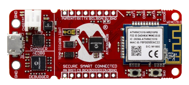
The PIC-IoT WG, manufactured by Microchip, is a wireless gateway designed specifically for Internet of Things (IoT) applications. It integrates a microcontroller, a Wi-Fi module, and a secure element to enable seamless connectivity between IoT devices and cloud platforms. This component is ideal for prototyping and deploying IoT solutions, offering a robust platform for data collection, processing, and transmission.
Explore Projects Built with PIC-IoT WG
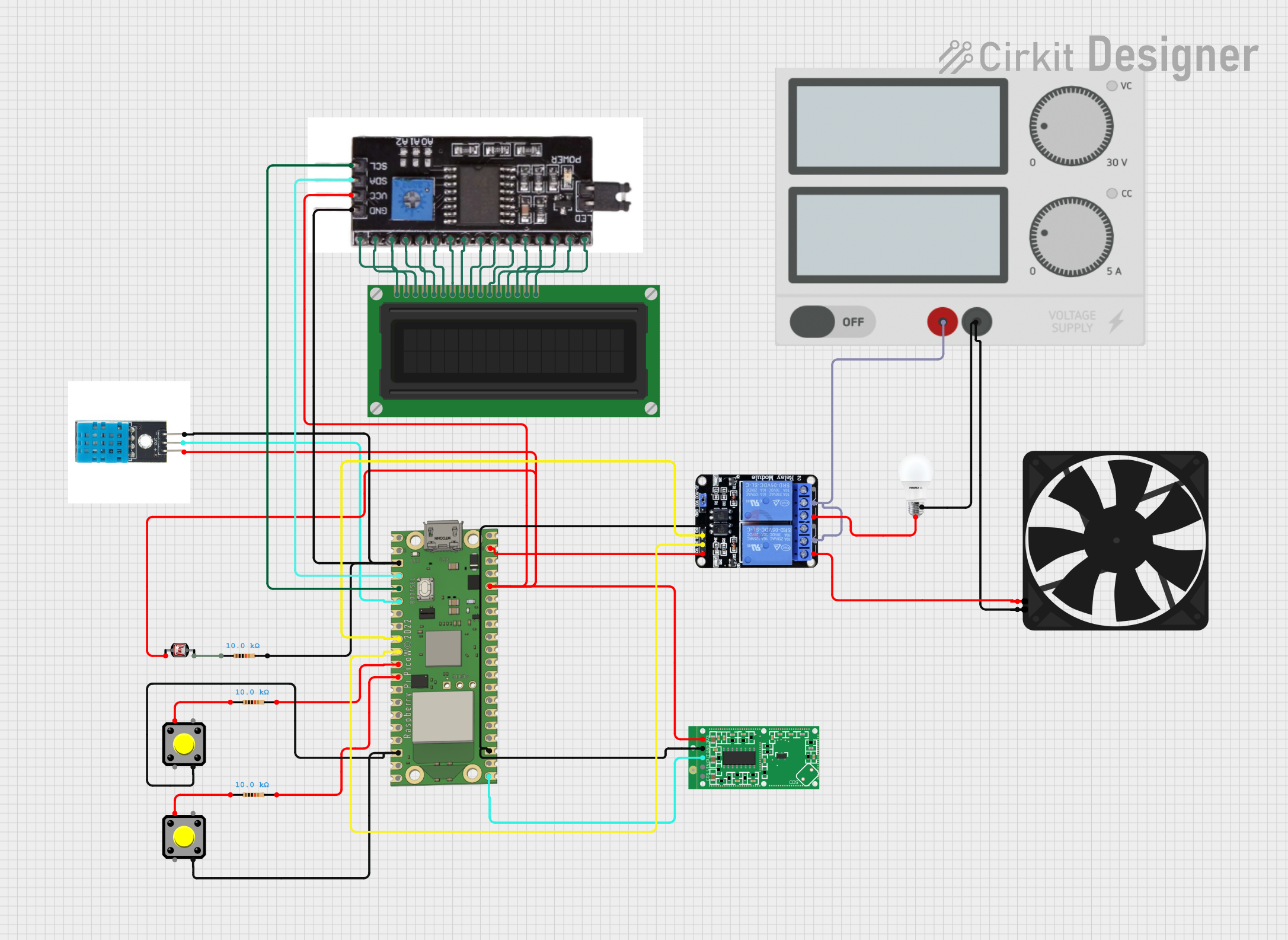
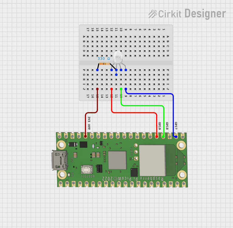
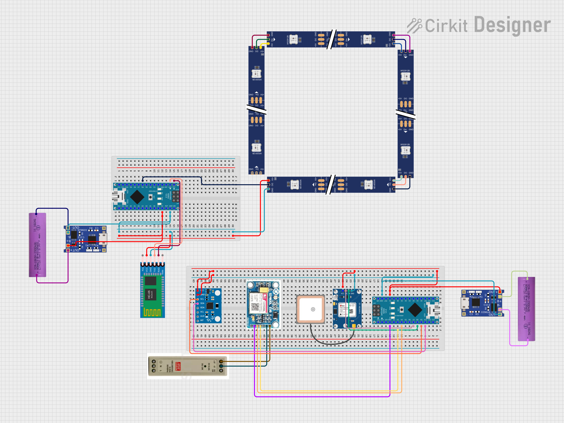
Explore Projects Built with PIC-IoT WG
Common Applications and Use Cases
- Smart home automation systems
- Industrial IoT (IIoT) monitoring and control
- Environmental monitoring and data logging
- Wearable devices and health monitoring
- Prototyping IoT solutions with cloud connectivity
Technical Specifications
Key Technical Details
| Parameter | Specification |
|---|---|
| Microcontroller | PIC24FJ128GA705 (16-bit MCU) |
| Wi-Fi Module | ATWINC1510 (802.11 b/g/n) |
| Secure Element | ATECC608A (for secure authentication) |
| Operating Voltage | 3.3V |
| Power Supply | USB or external power source |
| Communication Protocols | UART, I2C, SPI |
| Cloud Support | AWS IoT, Google Cloud IoT, Microsoft Azure IoT |
| Dimensions | 50mm x 25mm |
| Operating Temperature | -40°C to +85°C |
Pin Configuration and Descriptions
| Pin Name | Pin Number | Description |
|---|---|---|
| VCC | 1 | Power supply input (3.3V) |
| GND | 2 | Ground |
| TX | 3 | UART Transmit |
| RX | 4 | UART Receive |
| SDA | 5 | I2C Data Line |
| SCL | 6 | I2C Clock Line |
| GPIO1 | 7 | General Purpose Input/Output |
| GPIO2 | 8 | General Purpose Input/Output |
| RESET | 9 | Reset pin for the module |
| WAKE | 10 | Wake-up pin for low-power operation |
Usage Instructions
How to Use the Component in a Circuit
- Powering the Module: Connect the VCC pin to a 3.3V power source and the GND pin to ground.
- Communication: Use the UART pins (TX and RX) for serial communication with a microcontroller or computer. Alternatively, use the I2C pins (SDA and SCL) for interfacing with other devices.
- Cloud Connectivity: Configure the Wi-Fi module to connect to your local network and set up cloud credentials for AWS, Google Cloud, or Azure.
- Secure Authentication: Utilize the ATECC608A secure element for encrypted communication and device authentication.
- Programming: Use Microchip’s MPLAB X IDE and Harmony Framework for programming the PIC24FJ128GA705 microcontroller.
Important Considerations and Best Practices
- Ensure the power supply is stable and within the specified voltage range (3.3V).
- Use decoupling capacitors near the VCC pin to reduce noise and improve stability.
- Avoid placing the module near high-frequency or high-power components to minimize interference.
- When using the Wi-Fi module, ensure a clear line of sight for better signal strength.
- Regularly update the firmware to ensure compatibility with cloud services and security patches.
Example: Connecting to an Arduino UNO
The PIC-IoT WG can be connected to an Arduino UNO via UART. Below is an example code snippet for establishing communication:
#include <SoftwareSerial.h>

// Define RX and TX pins for SoftwareSerial
SoftwareSerial picIotSerial(10, 11); // RX = pin 10, TX = pin 11

void setup() {
  Serial.begin(9600); // Initialize Serial Monitor
  picIotSerial.begin(9600); // Initialize PIC-IoT communication

  Serial.println("Initializing PIC-IoT WG...");
  delay(1000);

  // Send a test command to the PIC-IoT WG
  picIotSerial.println("AT+GMR"); // Example AT command to get firmware version
}

void loop() {
  // Check if data is available from PIC-IoT WG
  if (picIotSerial.available()) {
    String response = picIotSerial.readString();
    Serial.println("Response from PIC-IoT WG: " + response);
  }

  // Add a delay to avoid flooding the serial monitor
  delay(500);
}
Notes:
- Connect the TX pin of the PIC-IoT WG to the RX pin of the Arduino UNO and vice versa.
- Use a level shifter if the Arduino operates at 5V logic levels to avoid damaging the PIC-IoT WG.
Troubleshooting and FAQs
Common Issues and Solutions
Module Not Powering On
- Ensure the VCC pin is connected to a stable 3.3V power source.
- Check for loose connections or damaged wires.
Wi-Fi Connection Fails
- Verify the SSID and password of the Wi-Fi network.
- Ensure the Wi-Fi module is within range of the router.
- Check for interference from other devices operating on the same frequency.
No Response from UART
- Confirm the baud rate settings match between the PIC-IoT WG and the microcontroller.
- Check the TX and RX connections for proper orientation.
Cloud Connectivity Issues
- Verify the cloud credentials and configuration.
- Ensure the device has internet access through the connected Wi-Fi network.
- Check for firewall or network restrictions that may block communication.
FAQs
Q: Can the PIC-IoT WG operate on 5V?
A: No, the module operates at 3.3V. Using 5V may damage the component. Use a voltage regulator or level shifter if necessary.
Q: Is the firmware upgradable?
A: Yes, the firmware can be updated using Microchip’s tools to ensure compatibility and security.
Q: Can I use the PIC-IoT WG with other microcontrollers?
A: Yes, the module can interface with any microcontroller that supports UART, I2C, or SPI communication.
Q: Does the module support Bluetooth?
A: No, the PIC-IoT WG is designed for Wi-Fi connectivity only.
Q: How do I reset the module?
A: Use the RESET pin to perform a hardware reset or send the appropriate AT command for a software reset.