How to Use relay 2 chanel 5v: Examples, Pinouts, and Specs
Introduction
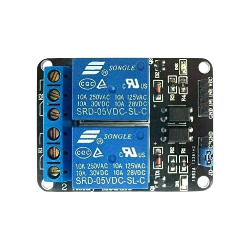
The Relay 2 Channel 5V module is an electronic component designed to control high-voltage devices using low-voltage signals. It features two independent relays, each capable of switching devices such as lights, fans, or other appliances. This module is widely used in home automation, industrial control systems, and IoT projects. Its ability to isolate low-voltage control circuits from high-voltage loads ensures safety and reliability in various applications.
Explore Projects Built with relay 2 chanel 5v


Explore Projects Built with relay 2 chanel 5v
Common Applications
- Home automation systems (e.g., controlling lights or appliances)
- Industrial equipment control
- IoT projects for remote device management
- Robotics and mechatronics
- Smart energy management systems
Technical Specifications
Key Technical Details
- Operating Voltage: 5V DC
- Trigger Voltage: 3.3V to 5V (compatible with most microcontrollers)
- Relay Channels: 2
- Relay Type: SPDT (Single Pole Double Throw)
- Maximum Load (per channel):
- AC: 250V at 10A
- DC: 30V at 10A
- Isolation: Optocoupler isolation for safe operation
- Dimensions: Approximately 50mm x 40mm x 20mm
- Indicator LEDs: Power and relay status indicators
Pin Configuration and Descriptions
Input Pins (Control Side)
| Pin Name | Description |
|---|---|
| VCC | Connect to 5V DC power supply. |
| GND | Connect to ground. |
| IN1 | Control signal for Relay 1. A HIGH signal activates the relay. |
| IN2 | Control signal for Relay 2. A HIGH signal activates the relay. |
Output Pins (Load Side - Per Relay)
| Pin Name | Description |
|---|---|
| COM | Common terminal for the relay. Connect to the power source or load. |
| NO | Normally Open terminal. Connect to the load for default OFF state. |
| NC | Normally Closed terminal. Connect to the load for default ON state. |
Usage Instructions
How to Use the Relay Module in a Circuit
Power the Module:
- Connect the VCC pin to a 5V DC power supply and the GND pin to ground.
- Ensure the power supply can provide sufficient current for the relays.
Connect the Control Signals:
- Use a microcontroller (e.g., Arduino UNO) or other control circuits to send signals to the IN1 and IN2 pins.
- A HIGH signal (3.3V to 5V) activates the corresponding relay.
Connect the Load:
- Identify the load you want to control (e.g., a light bulb or motor).
- Connect one terminal of the load to the COM pin of the relay.
- Connect the other terminal of the load to either the NO or NC pin, depending on the desired default state:
- NO (Normally Open): The load is OFF by default and turns ON when the relay is activated.
- NC (Normally Closed): The load is ON by default and turns OFF when the relay is activated.
Test the Circuit:
- Power on the circuit and send control signals to the IN1 and IN2 pins to toggle the relays.
- Observe the indicator LEDs to verify relay activation.
Important Considerations and Best Practices
- Isolation: Ensure proper isolation between the low-voltage control side and the high-voltage load side to prevent damage or hazards.
- Current Ratings: Do not exceed the maximum current and voltage ratings of the relays.
- Flyback Diodes: For inductive loads (e.g., motors), use flyback diodes to protect the relay from voltage spikes.
- Secure Connections: Use proper connectors or soldering to ensure reliable connections, especially on the high-voltage side.
Example Code for Arduino UNO
// Example code to control a 2-channel relay module with Arduino UNO
// IN1 and IN2 are connected to digital pins 7 and 8, respectively.

#define RELAY1 7  // Define pin for Relay 1 control
#define RELAY2 8  // Define pin for Relay 2 control

void setup() {
  pinMode(RELAY1, OUTPUT); // Set Relay 1 pin as output
  pinMode(RELAY2, OUTPUT); // Set Relay 2 pin as output

  // Initialize relays to OFF state
  digitalWrite(RELAY1, LOW);
  digitalWrite(RELAY2, LOW);
}

void loop() {
  // Turn on Relay 1 for 2 seconds
  digitalWrite(RELAY1, HIGH); // Activate Relay 1
  delay(2000);                // Wait for 2 seconds

  // Turn off Relay 1 and turn on Relay 2 for 2 seconds
  digitalWrite(RELAY1, LOW);  // Deactivate Relay 1
  digitalWrite(RELAY2, HIGH); // Activate Relay 2
  delay(2000);                // Wait for 2 seconds

  // Turn off both relays
  digitalWrite(RELAY2, LOW);  // Deactivate Relay 2
  delay(2000);                // Wait for 2 seconds
}
Troubleshooting and FAQs
Common Issues and Solutions
Relays Not Activating:
- Cause: Insufficient power supply or incorrect wiring.
- Solution: Verify that the VCC and GND pins are properly connected to a 5V power source. Check the control signal voltage (3.3V to 5V is required).
Indicator LEDs Not Lighting Up:
- Cause: Faulty module or incorrect power connection.
- Solution: Ensure the module is receiving 5V power. Test with a multimeter to confirm voltage levels.
Load Not Switching:
- Cause: Incorrect wiring on the load side.
- Solution: Double-check the connections to the COM, NO, and NC pins. Ensure the load is within the relay's voltage and current ratings.
Microcontroller Resetting When Relay Activates:
- Cause: Voltage spikes or insufficient power supply.
- Solution: Use a separate power supply for the relay module or add a capacitor to stabilize the power supply.
FAQs
Q: Can I use this module with a 3.3V microcontroller?
A: Yes, the module is compatible with 3.3V control signals, but ensure the VCC pin is powered with 5V.Q: Can I control AC and DC loads simultaneously?
A: Yes, as long as each relay's load does not exceed its maximum ratings.Q: Is it safe to use this module for high-power appliances?
A: Yes, but ensure proper isolation and do not exceed the relay's rated voltage and current.Q: Can I use this module to control a motor?
A: Yes, but for inductive loads like motors, use a flyback diode to protect the relay from voltage spikes.