How to Use ESP32-DEVKIT-V1: Examples, Pinouts, and Specs
Introduction
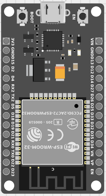
The ESP32-DEVKIT-V1, manufactured by Espressif Systems, is a versatile development board based on the powerful ESP32 chip. It features built-in Wi-Fi and Bluetooth capabilities, making it an ideal choice for IoT (Internet of Things) applications. The board is equipped with 30 pins, including multiple GPIOs, ADCs, and communication interfaces, enabling seamless integration with sensors, actuators, and other peripherals.
Explore Projects Built with ESP32-DEVKIT-V1


Explore Projects Built with ESP32-DEVKIT-V1
Common Applications and Use Cases
- IoT devices and smart home automation
- Wireless sensor networks
- Wearable technology
- Robotics and automation systems
- Prototyping and educational projects
- Bluetooth Low Energy (BLE) applications
Technical Specifications
The following table outlines the key technical specifications of the ESP32-DEVKIT-V1:
| Parameter | Specification |
|---|---|
| Microcontroller | ESP32 Dual-Core Xtensa LX6 |
| Clock Speed | Up to 240 MHz |
| Flash Memory | 4 MB (varies by model) |
| SRAM | 520 KB |
| Wi-Fi | 802.11 b/g/n (2.4 GHz) |
| Bluetooth | Bluetooth 4.2 and BLE |
| Operating Voltage | 3.3V |
| Input Voltage (VIN) | 5V (via USB or external power supply) |
| GPIO Pins | 30 pins |
| ADC Channels | 18 (12-bit resolution) |
| Communication Interfaces | UART, SPI, I2C, I2S, PWM |
| Power Consumption | Ultra-low power consumption in deep sleep mode (~10 µA) |
| Dimensions | 57 mm x 25 mm |
Pin Configuration and Descriptions
The ESP32-DEVKIT-V1 has a 30-pin layout. Below is the pin configuration:
| Pin Number | Pin Name | Description |
|---|---|---|
| 1 | EN | Reset pin (active high) |
| 2 | IO1 | GPIO1, used for UART TX |
| 3 | IO3 | GPIO3, used for UART RX |
| 4 | IO4 | GPIO4, supports PWM, ADC, and digital I/O |
| 5 | IO5 | GPIO5, supports PWM, ADC, and digital I/O |
| 6 | GND | Ground |
| 7 | VIN | Input voltage (5V) |
| 8 | IO12 | GPIO12, supports ADC, PWM, and digital I/O |
| 9 | IO13 | GPIO13, supports ADC, PWM, and digital I/O |
| 10 | IO14 | GPIO14, supports ADC, PWM, and digital I/O |
| 11 | IO15 | GPIO15, supports ADC, PWM, and digital I/O |
| 12 | IO16 | GPIO16, supports digital I/O |
| 13 | IO17 | GPIO17, supports digital I/O |
| 14 | IO18 | GPIO18, supports SPI and digital I/O |
| 15 | IO19 | GPIO19, supports SPI and digital I/O |
| 16 | IO21 | GPIO21, supports I2C SDA and digital I/O |
| 17 | IO22 | GPIO22, supports I2C SCL and digital I/O |
| 18 | IO23 | GPIO23, supports SPI and digital I/O |
| 19 | IO25 | GPIO25, supports ADC, PWM, and digital I/O |
| 20 | IO26 | GPIO26, supports ADC, PWM, and digital I/O |
| 21 | IO27 | GPIO27, supports ADC, PWM, and digital I/O |
| 22 | IO32 | GPIO32, supports ADC, PWM, and digital I/O |
| 23 | IO33 | GPIO33, supports ADC, PWM, and digital I/O |
| 24 | IO34 | GPIO34, input-only ADC |
| 25 | IO35 | GPIO35, input-only ADC |
| 26 | IO36 | GPIO36, input-only ADC |
| 27 | IO39 | GPIO39, input-only ADC |
| 28 | 3V3 | 3.3V output |
| 29 | GND | Ground |
| 30 | IO0 | GPIO0, used for boot mode selection |
Usage Instructions
How to Use the ESP32-DEVKIT-V1 in a Circuit
Powering the Board:
- Connect the board to your computer via a micro-USB cable for power and programming.
- Alternatively, supply 5V to the VIN pin and GND for external power.
Programming the Board:
- Install the Arduino IDE and add the ESP32 board support package.
- Select the correct board (
ESP32 Dev Module) and COM port in the Arduino IDE. - Write your code and upload it to the board.
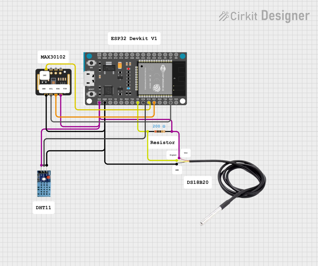
Connecting Peripherals:
- Use the GPIO pins to connect sensors, actuators, or other modules.
- Ensure that the voltage levels of connected devices are compatible with the ESP32 (3.3V logic).
Wi-Fi and Bluetooth Setup:
- Use the built-in libraries (
WiFi.handBluetoothSerial.h) to configure wireless communication.
- Use the built-in libraries (
Important Considerations and Best Practices
- Voltage Levels: The ESP32 operates at 3.3V logic. Avoid connecting 5V devices directly to GPIO pins without a level shifter.
- Boot Mode: GPIO0 must be pulled low during boot to enter programming mode.
- Power Supply: Ensure a stable power supply, especially when using Wi-Fi or Bluetooth, as these features can cause power spikes.
- Deep Sleep: Use deep sleep mode to conserve power in battery-powered applications.
Example Code for Arduino IDE
The following example demonstrates how to connect the ESP32 to a Wi-Fi network and print the IP address:
#include <WiFi.h> // Include the WiFi library

const char* ssid = "Your_SSID";       // Replace with your Wi-Fi network name
const char* password = "Your_Password"; // Replace with your Wi-Fi password

void setup() {
  Serial.begin(115200); // Initialize serial communication at 115200 baud
  delay(1000);          // Wait for a moment to stabilize

  Serial.println("Connecting to Wi-Fi...");
  WiFi.begin(ssid, password); // Start Wi-Fi connection

  while (WiFi.status() != WL_CONNECTED) {
    delay(500); // Wait until the connection is established
    Serial.print(".");
  }

  Serial.println("\nWi-Fi connected!");
  Serial.print("IP Address: ");
  Serial.println(WiFi.localIP()); // Print the assigned IP address
}

void loop() {
  // Add your main code here
}
Troubleshooting and FAQs
Common Issues and Solutions
The board is not detected by the computer:
- Ensure the USB cable is functional and supports data transfer.
- Install the correct USB-to-serial driver (e.g., CP2102 or CH340, depending on your board).
Upload fails with a timeout error:
- Press and hold the
BOOTbutton while uploading the code. - Check that the correct COM port and board are selected in the Arduino IDE.
- Press and hold the
Wi-Fi connection fails:
- Double-check the SSID and password.
- Ensure the Wi-Fi network is within range and operational.
GPIO pins not working as expected:
- Verify that the pins are not being used for other functions (e.g., boot mode).
- Check for short circuits or incorrect wiring.
FAQs
Can I use 5V sensors with the ESP32?
No, the ESP32 operates at 3.3V logic. Use a level shifter for 5V devices.What is the maximum current draw of the ESP32?
The ESP32 can draw up to 500 mA during peak operation (e.g., Wi-Fi transmission).How do I reset the board?
Press theENbutton to reset the ESP32.Can I use the ESP32 with other IDEs?
Yes, the ESP32 is compatible with other IDEs like PlatformIO and Espressif's own ESP-IDF.