How to Use Adafruit HMC5883L Triple-axis Magnetometer: Examples, Pinouts, and Specs
Introduction
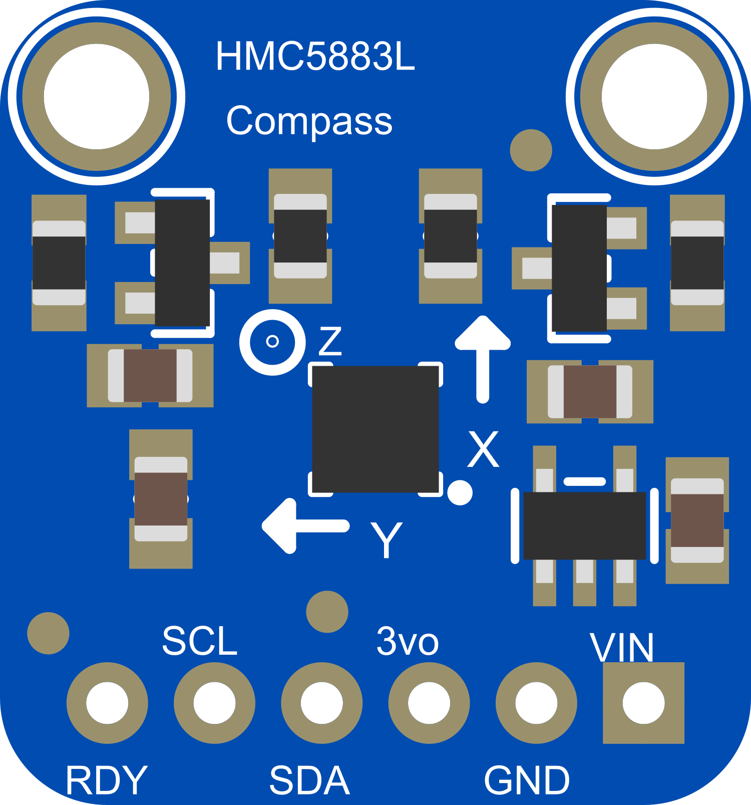
The Adafruit HMC5883L is a surface-mount, multi-chip module designed for low-field magnetic sensing with a digital interface for applications such as low-cost compassing and magnetometry. The HMC5883L includes our state-of-the-art, high-resolution HMC118X series magneto-resistive sensors plus an ASIC containing amplification, automatic degaussing strap drivers, offset cancellation, and a 12-bit ADC that enables 1° to 2° compass heading accuracy. The I²C serial bus allows for easy interface.
Explore Projects Built with Adafruit HMC5883L Triple-axis Magnetometer
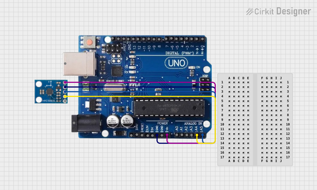
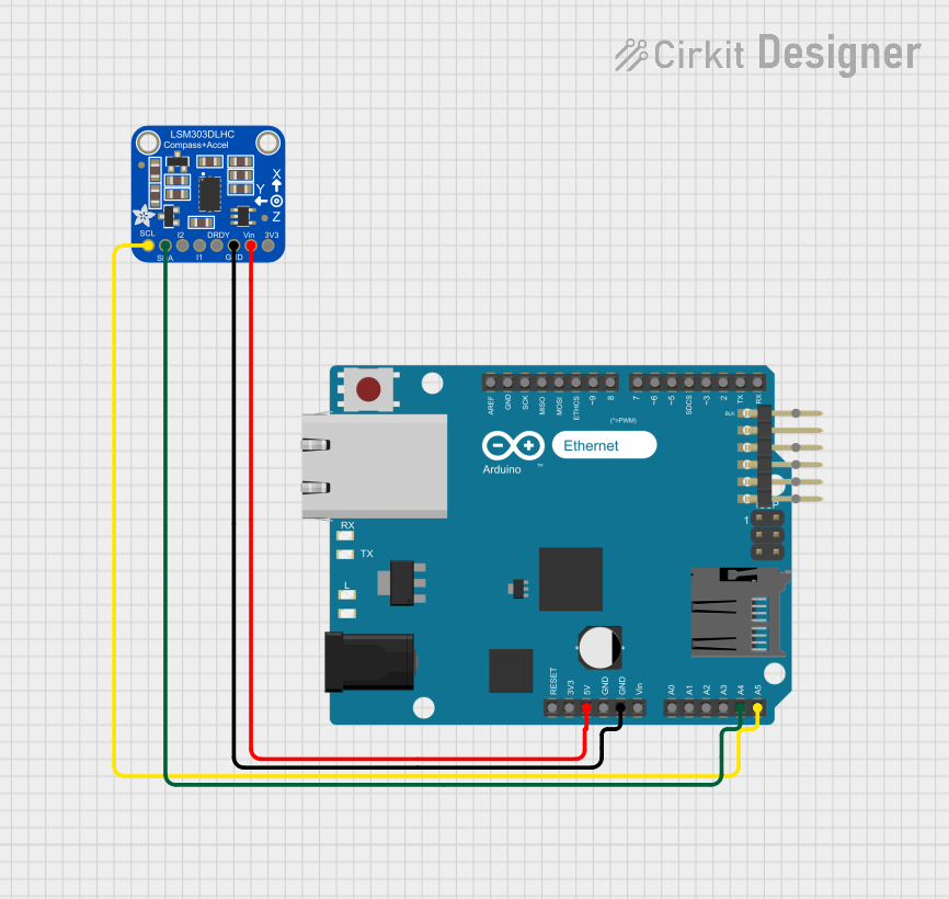

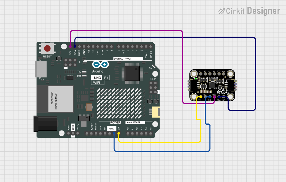
Explore Projects Built with Adafruit HMC5883L Triple-axis Magnetometer
Common Applications and Use Cases
- Electronic compasses
- Navigation systems
- Position detection
- Motion sensing and detection
- Robotics
Technical Specifications
Key Technical Details
- Power Supply: 2.16V to 3.6V
- Interface: I²C (up to 400kHz)
- Operating Temperature: -30°C to +85°C
- Magnetic Field Resolution: 5 milli-gauss
Pin Configuration and Descriptions
| Pin Number | Name | Description |
|---|---|---|
| 1 | VDD | Power supply (2.16V to 3.6V) |
| 2 | GND | Ground |
| 3 | SCL | Serial Clock Line for I²C |
| 4 | SDA | Serial Data Line for I²C |
| 5 | DRDY | Data Ready (optional use) |
Usage Instructions
How to Use the Component in a Circuit
Powering the Device:
- Connect VDD to a 2.16V to 3.6V power source.
- Connect GND to the ground of your power supply.
I²C Communication:
- Connect SCL to the I²C clock line on your microcontroller.
- Connect SDA to the I²C data line on your microcontroller.
Data Ready Pin (Optional):
- Connect DRDY to a digital input on your microcontroller if you wish to use the data ready feature.
Important Considerations and Best Practices
- Ensure that the power supply is within the specified range to prevent damage.
- Use pull-up resistors on the SCL and SDA lines as required by the I²C protocol.
- Place the magnetometer away from magnetic sources like motors and speakers.
- Calibrate the magnetometer for accurate readings in your specific environment.
Example Code for Arduino UNO
#include <Wire.h>
#include <HMC5883L.h>

HMC5883L magnetometer;

void setup() {
  Serial.begin(9600);
  Wire.begin();

  // Initialize HMC5883L
  magnetometer.initialize();

  // Verify connection
  if (magnetometer.testConnection()) {
    Serial.println("HMC5883L connected");
  } else {
    Serial.println("HMC5883L connection failed");
  }
}

void loop() {
  // Read magnetometer values
  int16_t mx, my, mz;
  magnetometer.getHeading(&mx, &my, &mz);

  // Output the results via the serial port
  Serial.print("X: "); Serial.print(mx);
  Serial.print(" Y: "); Serial.print(my);
  Serial.print(" Z: "); Serial.println(mz);

  delay(500);
}
Troubleshooting and FAQs
Common Issues Users Might Face
- Inaccurate Readings: Ensure that the magnetometer is calibrated and that there are no nearby magnetic sources affecting the readings.
- No Data on I²C: Check the connections and ensure pull-up resistors are in place. Also, verify that the correct I²C address is being used.
Solutions and Tips for Troubleshooting
- Calibration: Perform a calibration routine to account for any magnetic interference in your environment.
- Connection Issues: Double-check wiring, solder joints, and ensure that the microcontroller's I²C lines are functioning correctly.
FAQs
Q: What is the I²C address of the HMC5883L? A: The default I²C address of the HMC5883L is 0x1E.
Q: Can the HMC5883L be used with a 5V microcontroller? A: Yes, but a level shifter is recommended for the I²C lines to ensure compatibility with the HMC5883L's voltage levels.
Q: How do I know if the HMC5883L is functioning correctly?
A: Run the testConnection() method in the setup routine to verify communication with the device. If it returns true, the device is functioning correctly.
Q: How often should I calibrate the magnetometer? A: Calibration should be performed whenever the device is placed in a new environment or if there is a significant change in the surrounding magnetic field.