
How to Use TTL TO 485: Examples, Pinouts, and Specs
 Design with TTL TO 485 in Cirkit Designer
Introduction
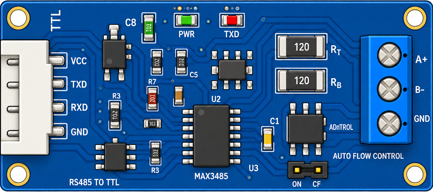
The TTL to RS-485 converter is an electronic module designed to convert TTL-level signals (typically 0–5V or 0–3.3V) into RS-485 differential signals. RS-485 is a robust communication standard widely used for long-distance and noise-resistant data transmission in industrial and embedded systems. This converter enables microcontrollers, such as Arduino or Raspberry Pi, to communicate over RS-485 networks.
Explore Projects Built with TTL TO 485
 Open Project in Cirkit Designer
 Open Project in Cirkit Designer
 Open Project in Cirkit Designer
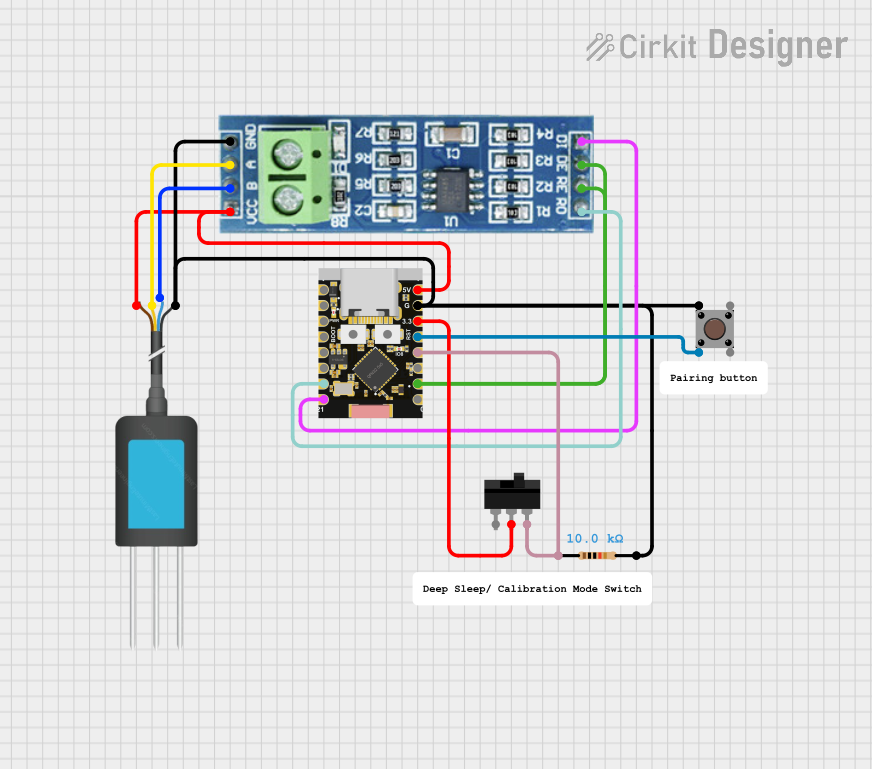 Open Project in Cirkit Designer
Explore Projects Built with TTL TO 485
Open Project in Cirkit DesignerOpen Project in Cirkit DesignerOpen Project in Cirkit DesignerOpen Project in Cirkit DesignerCommon Applications and Use Cases
- Industrial automation and control systems
- Long-distance serial communication (up to 1200 meters)
- Interfacing microcontrollers with RS-485 devices
- Building management systems (e.g., HVAC, lighting control)
- Modbus communication protocols
Technical Specifications
Key Technical Details
- Input Voltage (VCC): 3.3V or 5V
- Communication Standard: RS-485
- Baud Rate: Up to 115200 bps
- Transmission Distance: Up to 1200 meters (depending on cable quality and baud rate)
- Operating Temperature: -40°C to 85°C
- Power Consumption: Low power consumption, typically < 20mA
- Signal Direction Control: Automatic or manual (depending on the module)
Pin Configuration and Descriptions
The TTL to RS-485 converter typically has the following pin layout:
| Pin Name | Type | Description |
|---|---|---|
| VCC | Power Input | Connect to 3.3V or 5V power supply. |
| GND | Ground | Connect to the ground of the power supply. |
| TXD | Input | TTL-level transmit data from the microcontroller (e.g., Arduino TX pin). |
| RXD | Output | TTL-level receive data to the microcontroller (e.g., Arduino RX pin). |
| A (D+) | RS-485 Signal | Non-inverting RS-485 signal line. Connect to the A line of the RS-485 network. |
| B (D-) | RS-485 Signal | Inverting RS-485 signal line. Connect to the B line of the RS-485 network. |
| DE/RE | Control Signal | Optional. Used for manual direction control (if automatic control is not used). |
Note: Some modules may have additional pins or slightly different labels. Always refer to the specific module's datasheet for exact details.
Usage Instructions
How to Use the Component in a Circuit
Power the Module:
- Connect the
VCCpin to a 3.3V or 5V power supply, depending on your microcontroller's logic level. - Connect the
GNDpin to the ground of your power supply.
- Connect the
Connect TTL Signals:
- Connect the
TXDpin of the converter to theTXpin of your microcontroller. - Connect the
RXDpin of the converter to theRXpin of your microcontroller.
- Connect the
Connect RS-485 Signals:
- Connect the
A (D+)pin to the A line of the RS-485 network. - Connect the
B (D-)pin to the B line of the RS-485 network.
- Connect the
Direction Control:
- If the module supports automatic direction control, no additional connections are needed.
- If manual control is required, connect the
DE/REpin to a GPIO pin on your microcontroller and toggle it as needed:- HIGH: Transmit mode
- LOW: Receive mode
Termination Resistor:
- For long-distance communication, add a 120-ohm termination resistor between the A and B lines at both ends of the RS-485 network.
Example: Connecting to an Arduino UNO
Below is an example of how to use the TTL to RS-485 converter with an Arduino UNO for sending and receiving data.
Circuit Diagram
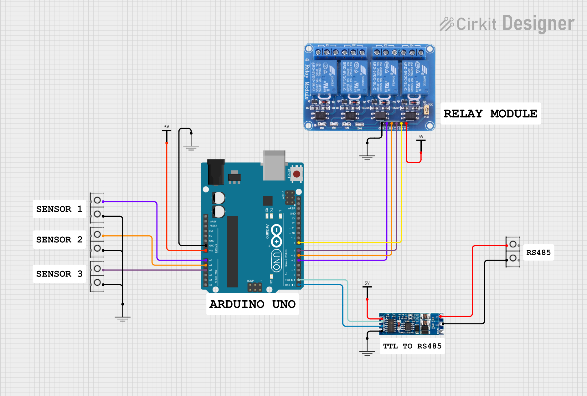
VCC→ 5V on ArduinoGND→ GND on ArduinoTXD→ Pin 1 (TX) on ArduinoRXD→ Pin 0 (RX) on ArduinoA (D+)→ RS-485 A lineB (D-)→ RS-485 B line
Arduino Code Example
// Include the SoftwareSerial library for serial communication
#include <SoftwareSerial.h>

// Define RX and TX pins for SoftwareSerial
SoftwareSerial RS485Serial(10, 11); // RX = Pin 10, TX = Pin 11

void setup() {
  // Initialize hardware serial for debugging
  Serial.begin(9600);
  // Initialize RS-485 serial communication
  RS485Serial.begin(9600);

  Serial.println("RS-485 Communication Initialized");
}

void loop() {
  // Send data over RS-485
  RS485Serial.println("Hello, RS-485!");

  // Check if data is available from RS-485
  if (RS485Serial.available()) {
    String receivedData = RS485Serial.readString();
    Serial.print("Received: ");
    Serial.println(receivedData);
  }

  delay(1000); // Wait for 1 second
}
Note: Use
SoftwareSerialif the hardware serial pins (0 and 1) are already in use. Adjust the pin numbers accordingly.
Important Considerations and Best Practices
- Ensure the RS-485 network is properly terminated with 120-ohm resistors at both ends to prevent signal reflections.
- Use twisted-pair cables for RS-485 connections to minimize noise and interference.
- Avoid connecting multiple RS-485 devices without proper addressing or collision management.
- Verify the baud rate and communication settings (e.g., parity, stop bits) match across all devices in the RS-485 network.
Troubleshooting and FAQs
Common Issues and Solutions
No Communication Between Devices:
- Verify the wiring of the A (D+) and B (D-) lines. Swapping these lines can cause communication failure.
- Check the power supply voltage and ensure the module is powered correctly.
Data Corruption or Noise:
- Ensure proper termination resistors are installed at both ends of the RS-485 network.
- Use shielded or twisted-pair cables for long-distance communication.
Direction Control Issues:
- If using manual direction control, ensure the
DE/REpin is toggled correctly for transmit and receive modes.
- If using manual direction control, ensure the
Module Overheating:
- Check for short circuits or excessive current draw on the RS-485 lines.
FAQs
Q: Can I use this module with a 3.3V microcontroller?
A: Yes, the module supports both 3.3V and 5V logic levels. Ensure the VCC pin is connected to the appropriate voltage.
Q: How many devices can I connect to an RS-485 network?
A: RS-485 supports up to 32 devices on a single network without repeaters. For larger networks, use RS-485 repeaters.
Q: What is the maximum baud rate supported?
A: The module typically supports baud rates up to 115200 bps, but this may vary depending on the specific model.
Q: Do I need to manually control the direction pin?
A: Many TTL to RS-485 converters have automatic direction control. If your module requires manual control, use a GPIO pin to toggle the DE/RE pin.
By following this documentation, you can effectively integrate the TTL to RS-485 converter into your projects for reliable long-distance communication.