How to Use Gear Motor with integrated Encoder: Examples, Pinouts, and Specs

Introduction
The Naroote Gear Motor with Integrated Encoder is a versatile and efficient component that combines a DC motor, a gearbox, and an encoder into a single unit. The gearbox reduces the motor's speed while increasing its torque, making it suitable for applications requiring high torque and precise control. The integrated encoder provides feedback on the motor's position and speed, enabling closed-loop control for enhanced accuracy.
This component is widely used in robotics, automation systems, conveyor belts, and other applications where precise motion control is essential. Its compact design and integrated functionality make it a popular choice for engineers and hobbyists alike.
Explore Projects Built with Gear Motor with integrated Encoder

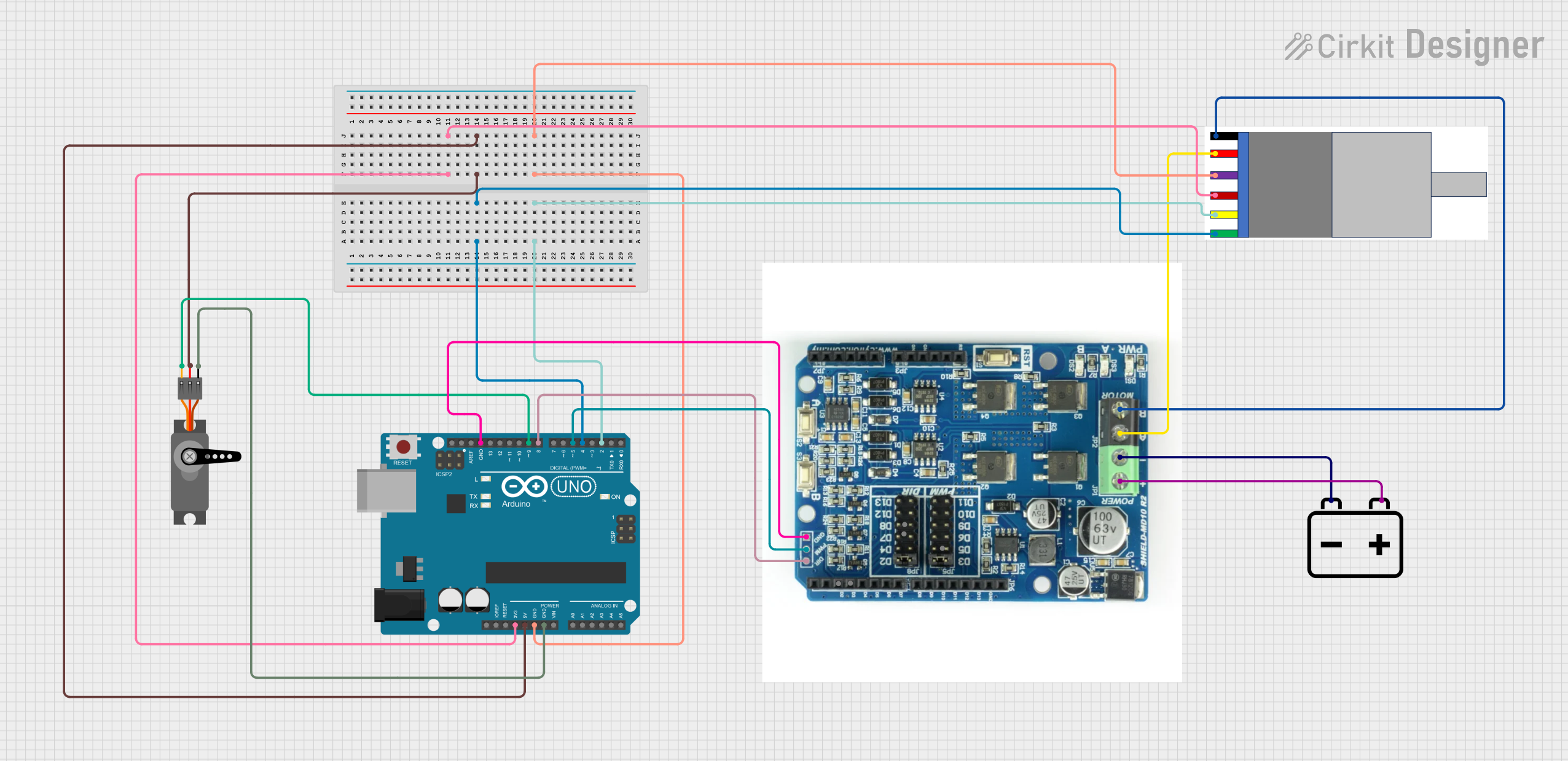
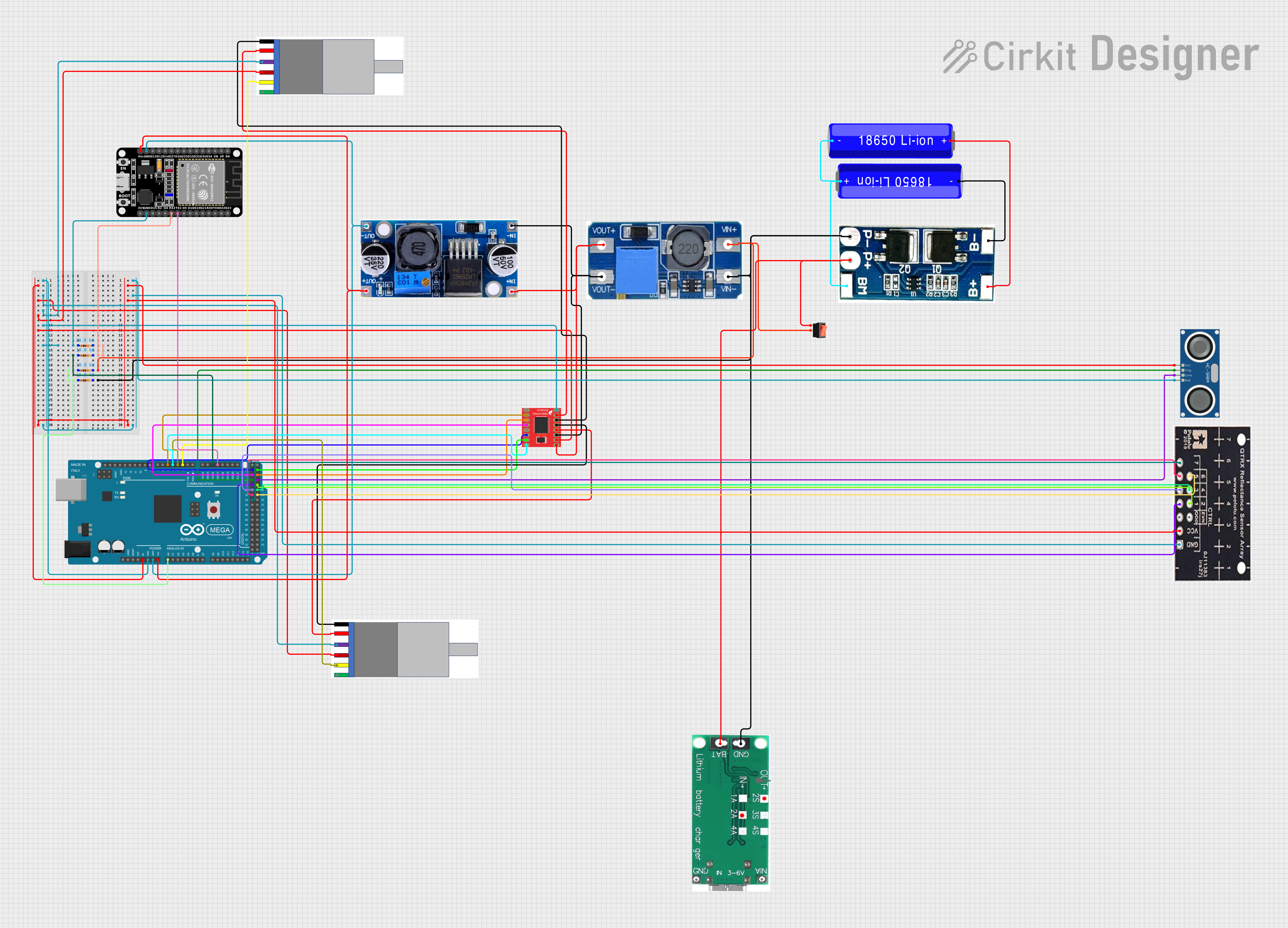
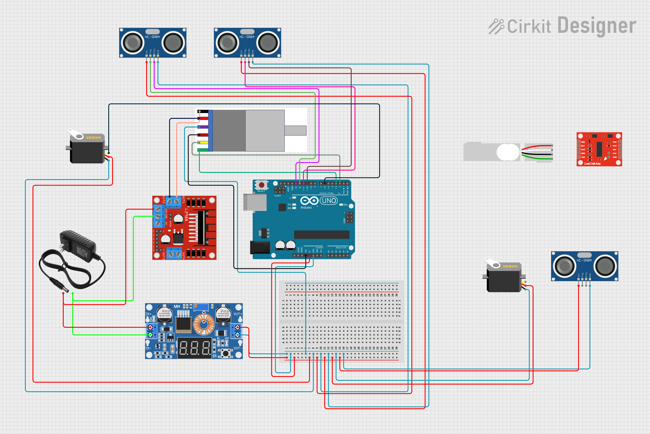
Explore Projects Built with Gear Motor with integrated Encoder
Technical Specifications
Below are the key technical details of the Naroote Gear Motor with Integrated Encoder:
General Specifications
- Operating Voltage: 6V to 12V DC
- No-Load Speed: 100 RPM to 500 RPM (varies by model)
- Torque: Up to 10 kg·cm (depending on the gearbox ratio)
- Encoder Resolution: 11 pulses per revolution (PPR) per channel
- Gearbox Ratio: 1:30, 1:50, or 1:100 (varies by model)
- Current Consumption:
- No-Load: ~100 mA
- Stall: ~1.2 A
- Shaft Diameter: 6 mm
- Weight: ~150 g
Pin Configuration and Descriptions
The motor typically comes with a 6-pin connector for the encoder and two additional terminals for the motor power. Below is the pinout:
Motor Power Terminals
| Terminal | Description |
|---|---|
| M+ | Motor positive terminal |
| M- | Motor negative terminal |
Encoder Pinout
| Pin Number | Label | Description |
|---|---|---|
| 1 | VCC | Power supply for the encoder (5V) |
| 2 | GND | Ground |
| 3 | A | Encoder channel A output |
| 4 | B | Encoder channel B output |
| 5 | I | Index pulse (optional, not always available) |
| 6 | NC | Not connected (reserved for future use) |
Usage Instructions
How to Use the Component in a Circuit
- Power the Motor: Connect the motor terminals (M+ and M-) to a DC power supply or motor driver. Ensure the voltage matches the motor's operating range (6V to 12V).
- Connect the Encoder:
- Provide 5V to the encoder's VCC pin and connect the GND pin to the circuit ground.
- Connect the encoder's A and B pins to the microcontroller or motor driver for position and speed feedback.
- Control the Motor:
- Use a motor driver or H-bridge to control the motor's speed and direction.
- Read the encoder signals (A and B) to monitor the motor's position and speed.
Important Considerations and Best Practices
- Power Supply: Use a stable power supply to avoid voltage fluctuations that could damage the motor or encoder.
- Current Limiting: Ensure your motor driver can handle the stall current (~1.2 A) to prevent damage.
- Debouncing: Implement software debouncing for the encoder signals to avoid false readings caused by noise.
- Mounting: Securely mount the motor to prevent vibrations that could affect encoder accuracy.
- Wiring: Keep encoder wires short and shielded to minimize interference.
Example Code for Arduino UNO
Below is an example of how to use the Naroote Gear Motor with Integrated Encoder with an Arduino UNO to read encoder signals and control the motor:
// Example code to read encoder signals and control the motor
// Connect encoder pins A and B to Arduino pins 2 and 3
// Connect motor terminals to a motor driver controlled by Arduino pins 9 and 10

#define ENCODER_PIN_A 2  // Encoder channel A connected to pin 2
#define ENCODER_PIN_B 3  // Encoder channel B connected to pin 3
#define MOTOR_PWM 9      // Motor PWM control pin
#define MOTOR_DIR 10     // Motor direction control pin

volatile int encoderCount = 0;  // Variable to store encoder count

void setup() {
  pinMode(ENCODER_PIN_A, INPUT_PULLUP);  // Set encoder A pin as input
  pinMode(ENCODER_PIN_B, INPUT_PULLUP);  // Set encoder B pin as input
  pinMode(MOTOR_PWM, OUTPUT);           // Set motor PWM pin as output
  pinMode(MOTOR_DIR, OUTPUT);           // Set motor direction pin as output

  // Attach interrupt to encoder A pin
  attachInterrupt(digitalPinToInterrupt(ENCODER_PIN_A), encoderISR, CHANGE);

  Serial.begin(9600);  // Initialize serial communication
}

void loop() {
  // Example: Set motor speed and direction
  digitalWrite(MOTOR_DIR, HIGH);  // Set motor direction
  analogWrite(MOTOR_PWM, 128);   // Set motor speed (0-255)

  // Print encoder count to the serial monitor
  Serial.print("Encoder Count: ");
  Serial.println(encoderCount);

  delay(100);  // Delay for readability
}

// Interrupt Service Routine (ISR) for encoder
void encoderISR() {
  // Read encoder B pin to determine direction
  if (digitalRead(ENCODER_PIN_B) == HIGH) {
    encoderCount++;  // Increment count for forward rotation
  } else {
    encoderCount--;  // Decrement count for reverse rotation
  }
}
Troubleshooting and FAQs
Common Issues and Solutions
Motor Not Spinning:
- Cause: Insufficient power supply or incorrect wiring.
- Solution: Verify the power supply voltage and check the motor connections.
Encoder Not Providing Feedback:
- Cause: Incorrect wiring or damaged encoder.
- Solution: Ensure the encoder pins are correctly connected to the microcontroller. Check for loose or damaged wires.
Noisy Encoder Signals:
- Cause: Electrical noise or long unshielded wires.
- Solution: Use shielded cables for the encoder and implement software debouncing.
Motor Overheating:
- Cause: Prolonged operation at high current or stall conditions.
- Solution: Avoid stalling the motor and ensure proper ventilation.
FAQs
Q: Can I use this motor with a 3.3V microcontroller?
- A: Yes, but you will need a level shifter to interface the 5V encoder signals with the 3.3V microcontroller.
Q: How do I calculate the motor's speed using the encoder?
- A: Count the encoder pulses over a fixed time interval and multiply by the encoder resolution and gearbox ratio.
Q: Can I use this motor for continuous rotation?
- A: Yes, the motor is designed for continuous operation, provided it is not overloaded or stalled.
This concludes the documentation for the Naroote Gear Motor with Integrated Encoder.