How to Use Step Up Boost Liion Battery Charger Board DDTCCRUB 3S2A: Examples, Pinouts, and Specs
Introduction
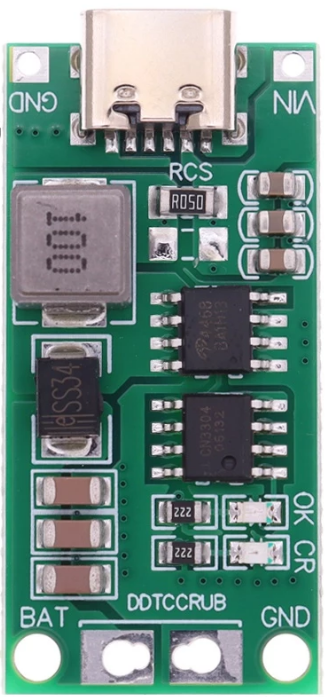
The Step Up Boost Li-ion Battery Charger Board DDTCCRUB 3S2A is a specialized circuit board designed to charge lithium-ion batteries efficiently. It features a step-up voltage converter that supports 3 cells in series (3S) and provides a maximum output current of 2A. This component is ideal for applications requiring compact, reliable, and efficient charging solutions for multi-cell lithium-ion battery packs.
Explore Projects Built with Step Up Boost Liion Battery Charger Board DDTCCRUB 3S2A


Explore Projects Built with Step Up Boost Liion Battery Charger Board DDTCCRUB 3S2A
Common Applications and Use Cases
- Power banks and portable chargers
- DIY battery packs for robotics and drones
- Backup power systems
- Solar-powered battery charging systems
- Electric bicycles and scooters
Technical Specifications
Key Technical Details
- Input Voltage Range: 5V to 12V DC
- Output Voltage: 12.6V DC (for 3S lithium-ion battery packs)
- Maximum Output Current: 2A
- Charging Method: Constant Current (CC) and Constant Voltage (CV)
- Battery Configuration: 3S (3 cells in series)
- Efficiency: Up to 92% (depending on input voltage and load)
- Protection Features: Overcharge, overcurrent, and short-circuit protection
- Board Dimensions: 50mm x 25mm x 10mm (L x W x H)
Pin Configuration and Descriptions
| Pin Name | Description |
|---|---|
VIN+ |
Positive input voltage terminal (connect to DC power source, 5V-12V). |
VIN- |
Negative input voltage terminal (connect to ground of the power source). |
B+ |
Positive terminal for the 3S lithium-ion battery pack. |
B- |
Negative terminal for the 3S lithium-ion battery pack. |
OUT+ |
Positive output terminal (stepped-up voltage, 12.6V DC). |
OUT- |
Negative output terminal (ground for the output voltage). |
LED1 |
Charging status indicator (ON: Charging, OFF: Fully charged). |
LED2 |
Fault indicator (ON: Fault detected, e.g., overcurrent or short circuit). |
Usage Instructions
How to Use the Component in a Circuit
- Power Input: Connect a DC power source (5V-12V) to the
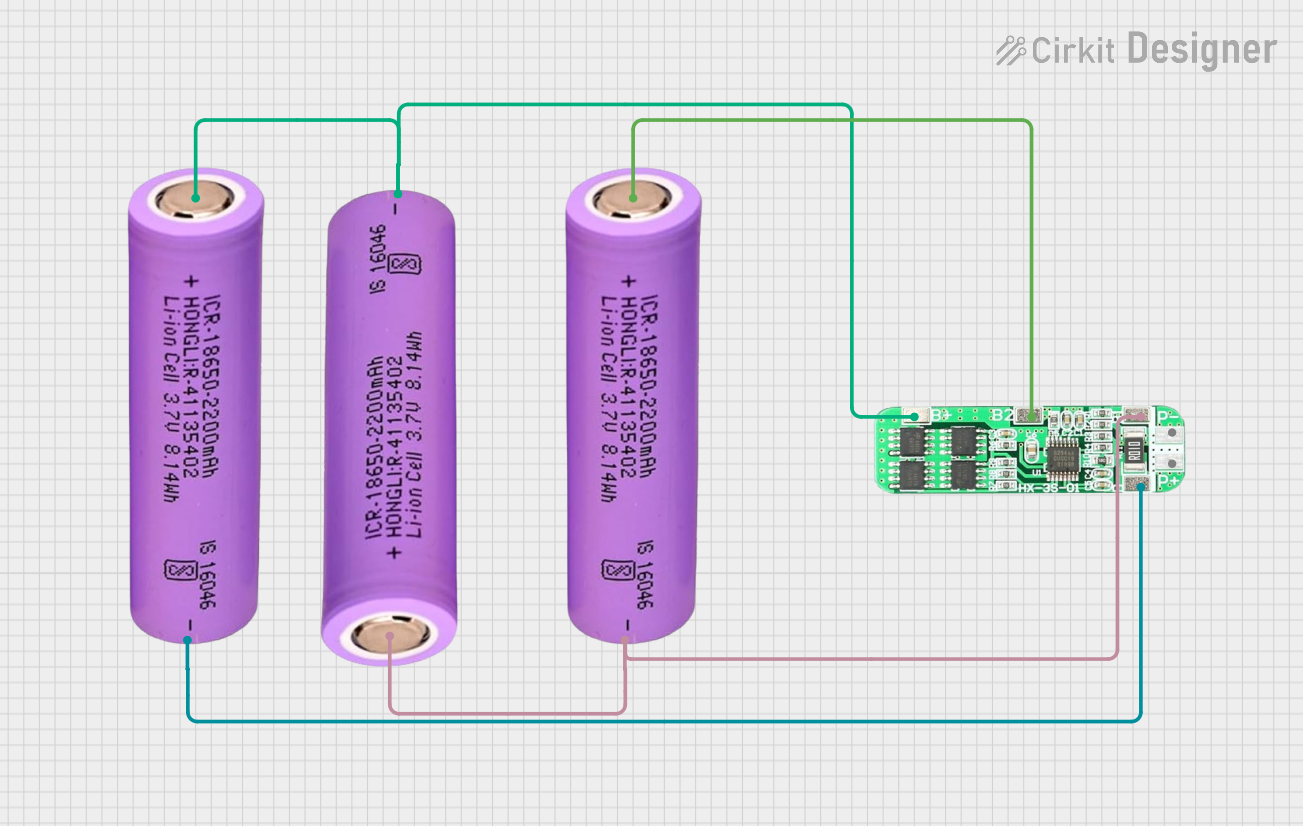
VIN+andVIN-pins. Ensure the power source can supply sufficient current (at least 2A). - Battery Connection: Connect the 3S lithium-ion battery pack to the
B+andB-terminals. Ensure the battery pack is properly balanced and within the supported voltage range. - Output Connection: If you need to power an external load, connect it to the
OUT+andOUT-terminals. The output voltage will be regulated to 12.6V. - Status Monitoring: Use the
LED1andLED2indicators to monitor the charging status and detect faults.
Important Considerations and Best Practices
- Input Voltage: Ensure the input voltage is within the specified range (5V-12V). Exceeding this range may damage the board.
- Battery Compatibility: Only use this board with 3S lithium-ion battery packs. Using incompatible batteries may result in improper charging or damage.
- Heat Dissipation: The board may heat up during operation. Ensure adequate ventilation or use a heatsink if necessary.
- Polarity: Double-check all connections for correct polarity before powering the board. Reversed connections can damage the component.
- Load Current: Do not exceed the maximum output current of 2A to avoid overloading the board.
Example: Using with an Arduino UNO
If you want to monitor the charging status using an Arduino UNO, you can connect the LED1 and LED2 pins to digital input pins on the Arduino. Below is an example code snippet:
// Define pins for LED indicators
const int chargingStatusPin = 2; // Connect to LED1
const int faultStatusPin = 3;    // Connect to LED2

void setup() {
  // Initialize serial communication for debugging
  Serial.begin(9600);

  // Set LED pins as input
  pinMode(chargingStatusPin, INPUT);
  pinMode(faultStatusPin, INPUT);
}

void loop() {
  // Read the status of the charging indicator
  int chargingStatus = digitalRead(chargingStatusPin);
  int faultStatus = digitalRead(faultStatusPin);

  // Print charging status to the serial monitor
  if (chargingStatus == HIGH) {
    Serial.println("Battery is charging...");
  } else {
    Serial.println("Battery is fully charged.");
  }

  // Print fault status to the serial monitor
  if (faultStatus == HIGH) {
    Serial.println("Fault detected! Check connections or load.");
  }

  // Add a small delay to avoid flooding the serial monitor
  delay(1000);
}
Troubleshooting and FAQs
Common Issues and Solutions
Board Not Powering On
- Cause: Insufficient input voltage or current.
- Solution: Verify that the input voltage is within the 5V-12V range and the power source can supply at least 2A.
Battery Not Charging
- Cause: Incorrect battery connection or incompatible battery pack.
- Solution: Ensure the battery pack is a 3S lithium-ion configuration and is properly connected to the
B+andB-terminals.
Overheating
- Cause: Prolonged operation at maximum current or poor ventilation.
- Solution: Reduce the load current or improve heat dissipation with a heatsink or fan.
Fault Indicator (LED2) is ON
- Cause: Overcurrent, short circuit, or other fault condition.
- Solution: Disconnect the load and check for wiring errors or excessive current draw.
FAQs
Can I use this board with a 2S or 4S battery pack?
- No, this board is specifically designed for 3S lithium-ion battery packs. Using it with other configurations may result in improper charging or damage.
What happens if the input voltage drops below 5V?
- The board may stop functioning or fail to charge the battery properly. Ensure a stable input voltage within the specified range.
Is it safe to leave the battery connected after it is fully charged?
- Yes, the board includes overcharge protection, so it is safe to leave the battery connected. However, it is recommended to disconnect the battery if not in use for extended periods.
Can I use this board to power a device while charging the battery?
- Yes, the board supports simultaneous charging and powering of a load, but ensure the total current does not exceed 2A.