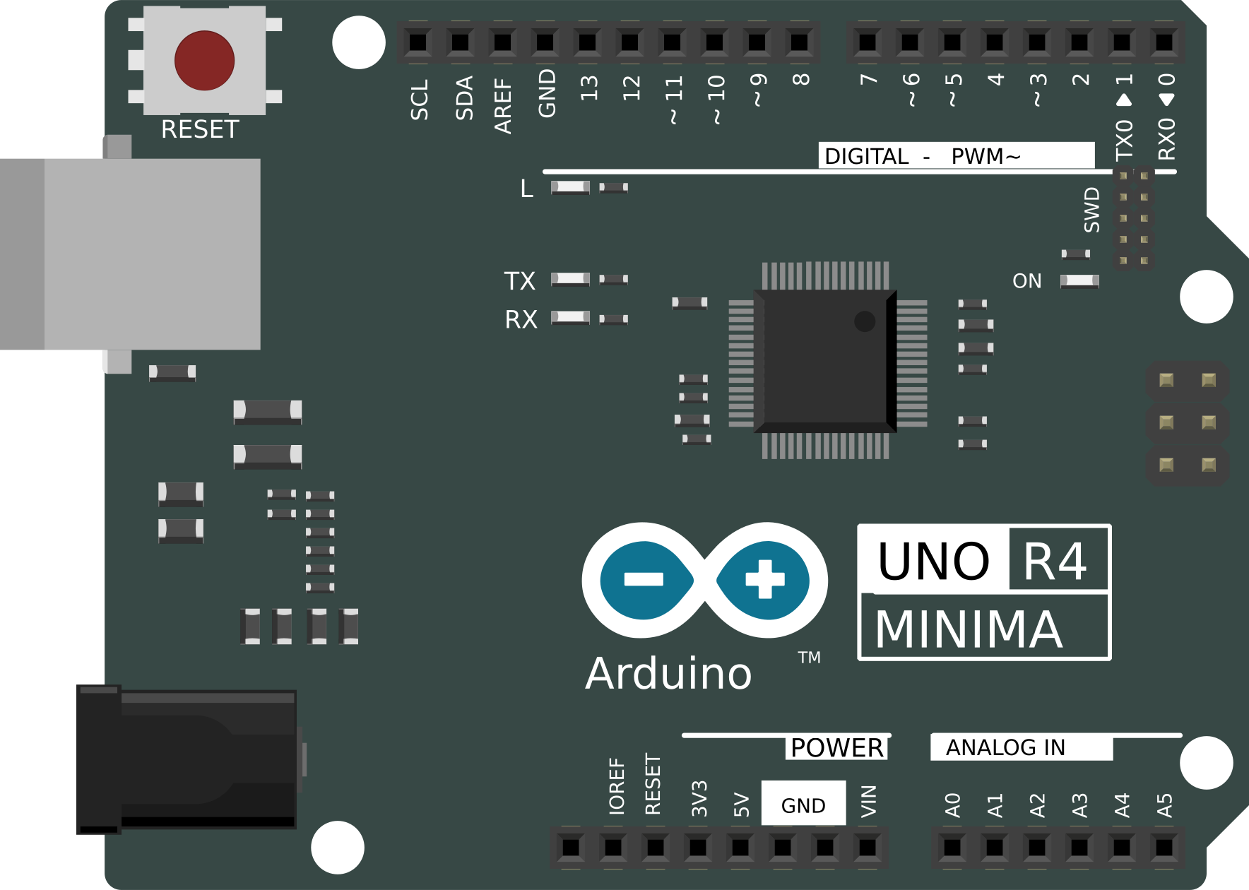
How to Use r4 minima: Examples, Pinouts, and Specs
Introduction
The R4 Minima is a compact, low-resistance resistor designed for use in electronic circuits. Its small size and low resistance value make it ideal for applications requiring precise current control and minimal power dissipation. The R4 Minima is commonly used in signal conditioning, current sensing, and as a pull-up or pull-down resistor in digital circuits. Its versatility and reliability make it a popular choice for both hobbyists and professional engineers.
Explore Projects Built with r4 minima
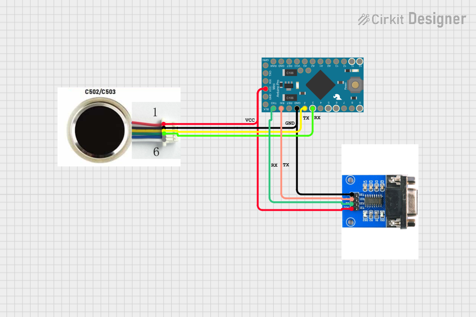
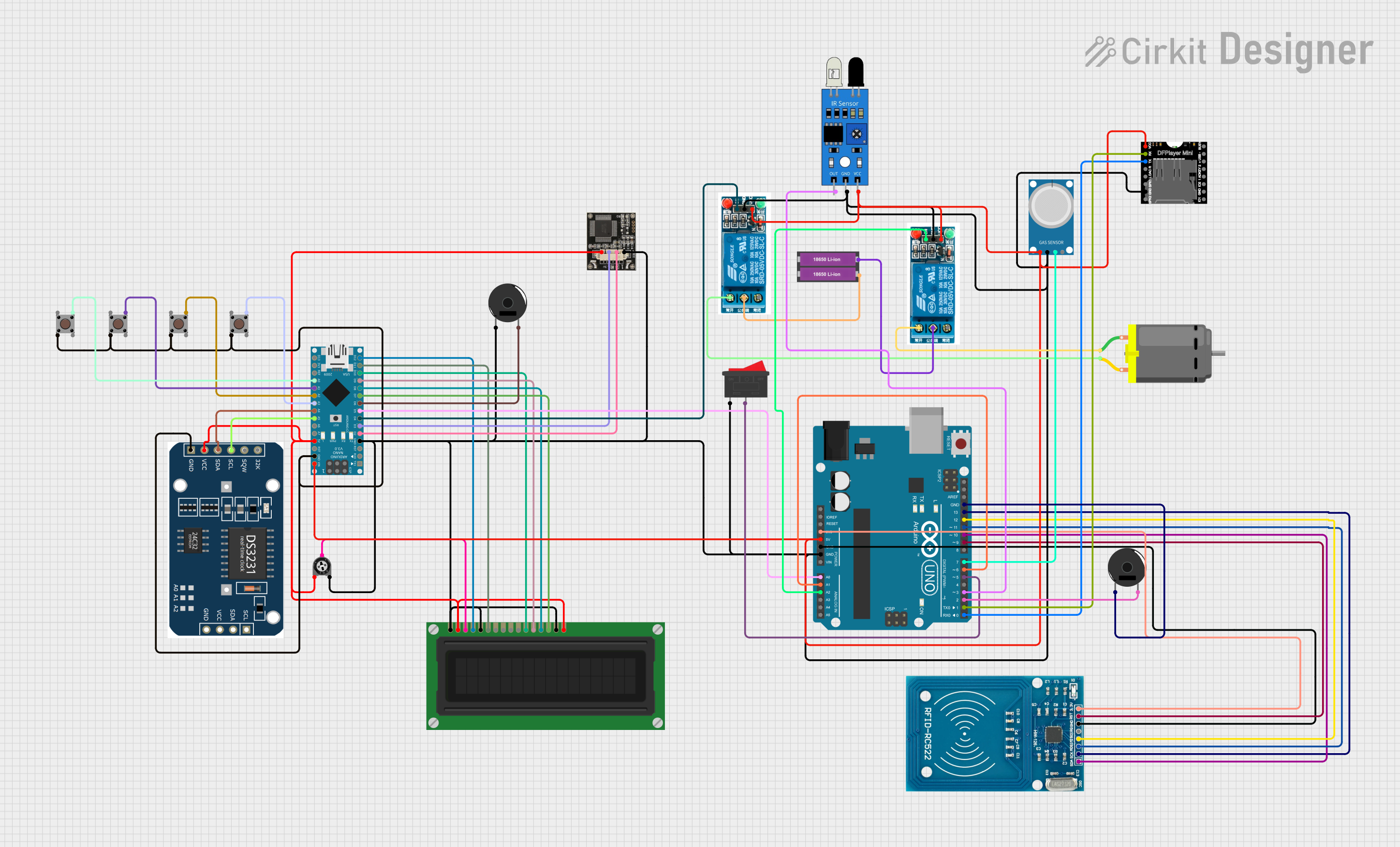
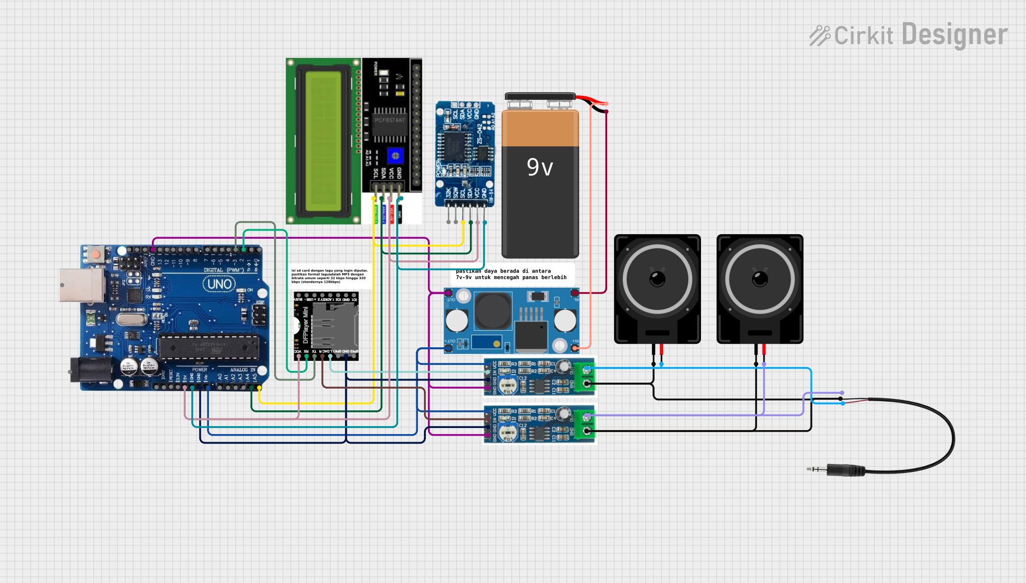

Explore Projects Built with r4 minima
Common Applications:
- Current sensing in low-power circuits
- Pull-up or pull-down resistor in digital logic circuits
- Voltage dividers in compact designs
- Signal conditioning in analog circuits
- Protection against inrush currents in sensitive components
Technical Specifications
Below are the key technical details of the R4 Minima resistor:
| Parameter | Value |
|---|---|
| Resistance Range | 0.1 Ω to 10 Ω |
| Power Rating | 0.125 W (1/8 W) |
| Tolerance | ±1% |
| Temperature Coefficient | ±100 ppm/°C |
| Operating Temperature | -55°C to +155°C |
| Package Type | Surface Mount (SMD) or Through-Hole |
| Dimensions (SMD) | 1.6 mm × 0.8 mm (0603 package) |
Pin Configuration and Descriptions
The R4 Minima is a two-terminal passive component. Below is the pin configuration:
| Pin | Description |
|---|---|
| Pin 1 | Connects to one side of the circuit |
| Pin 2 | Connects to the other side of the circuit |
Note: The R4 Minima does not have polarity, so the pins can be connected in either orientation.
Usage Instructions
How to Use the R4 Minima in a Circuit
- Determine the Required Resistance Value: Use Ohm's Law (V = IR) to calculate the resistance needed for your application.
- Select the Correct Power Rating: Ensure the resistor's power rating (0.125 W) is sufficient for the circuit's power dissipation requirements.
- Placement in the Circuit:
- For current sensing, place the R4 Minima in series with the load.
- For pull-up or pull-down applications, connect one terminal to the signal line and the other to the power rail or ground.
- Soldering: If using the SMD version, carefully solder the resistor onto the PCB pads. For through-hole versions, insert the leads into the PCB holes and solder them securely.
Important Considerations and Best Practices
- Avoid Overloading: Ensure the resistor does not exceed its power rating to prevent overheating or damage.
- Temperature Effects: Be mindful of the temperature coefficient, especially in high-temperature environments, as resistance may vary slightly.
- Verify Connections: Double-check the resistor's placement and solder joints to ensure proper functionality.
- Use in Arduino Projects: The R4 Minima is often used in Arduino circuits for pull-up/pull-down resistors or current-limiting applications.
Example: Using R4 Minima with Arduino UNO
Below is an example of using the R4 Minima as a pull-down resistor for a push button connected to an Arduino UNO:
// Define the pin for the push button
const int buttonPin = 2; // Digital pin 2 connected to the button

// Define the pin for the LED
const int ledPin = 13; // Built-in LED on pin 13

void setup() {
  pinMode(buttonPin, INPUT); // Set button pin as input
  pinMode(ledPin, OUTPUT);  // Set LED pin as output
}

void loop() {
  // Read the state of the button
  int buttonState = digitalRead(buttonPin);

  // If the button is pressed, turn on the LED
  if (buttonState == HIGH) {
    digitalWrite(ledPin, HIGH); // Turn on LED
  } else {
    digitalWrite(ledPin, LOW);  // Turn off LED
  }
}

/* Note: The R4 Minima is used as a pull-down resistor in this circuit.
   It ensures the button pin reads LOW when the button is not pressed.
   Connect one terminal of the R4 Minima to the button pin and the other
   terminal to ground. */
Troubleshooting and FAQs
Common Issues and Solutions
Resistor Overheating:
- Cause: Exceeding the power rating of the resistor.
- Solution: Use a resistor with a higher power rating or reduce the current in the circuit.
Incorrect Resistance Value:
- Cause: Using the wrong resistor or incorrect placement in the circuit.
- Solution: Double-check the resistor's value and ensure it matches the circuit requirements.
Poor Solder Joints:
- Cause: Improper soldering of the resistor leads or pads.
- Solution: Re-solder the connections, ensuring a clean and secure joint.
Circuit Not Functioning as Expected:
- Cause: Misplacement of the resistor or incorrect wiring.
- Solution: Verify the resistor's placement and connections using the circuit diagram.
FAQs
Q1: Can I use the R4 Minima in high-power circuits?
A1: No, the R4 Minima is designed for low-power applications with a maximum power rating of 0.125 W. For high-power circuits, use a resistor with a higher power rating.
Q2: Does the R4 Minima have polarity?
A2: No, the R4 Minima is a non-polarized component and can be connected in either orientation.
Q3: How do I calculate the power dissipation of the R4 Minima?
A3: Use the formula ( P = I^2 \times R ), where ( P ) is power, ( I ) is current, and ( R ) is resistance. Ensure the calculated power does not exceed 0.125 W.
Q4: Can I use the R4 Minima in high-frequency circuits?
A4: Yes, the R4 Minima can be used in high-frequency circuits, but ensure its parasitic inductance and capacitance are negligible for your application.
By following this documentation, you can effectively integrate the R4 Minima resistor into your electronic designs.