
How to Use Teensy 3.1: Examples, Pinouts, and Specs
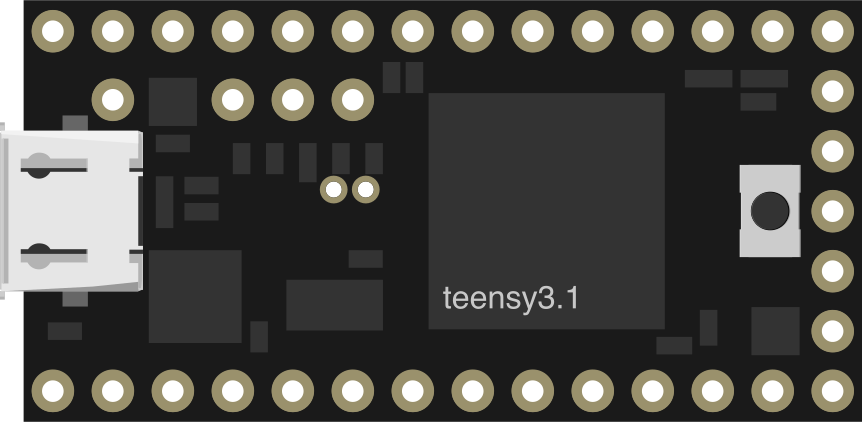
 Design with Teensy 3.1 in Cirkit Designer
Introduction
The Teensy 3.1 is a compact and powerful microcontroller board based on the ARM Cortex-M4 processor. It features 32KB of RAM, 256KB of flash memory, and built-in support for USB connectivity. This versatile board is designed for a wide range of embedded projects, including robotics, IoT devices, audio processing, and more. Its small form factor and high performance make it an excellent choice for both hobbyists and professionals.
Explore Projects Built with Teensy 3.1
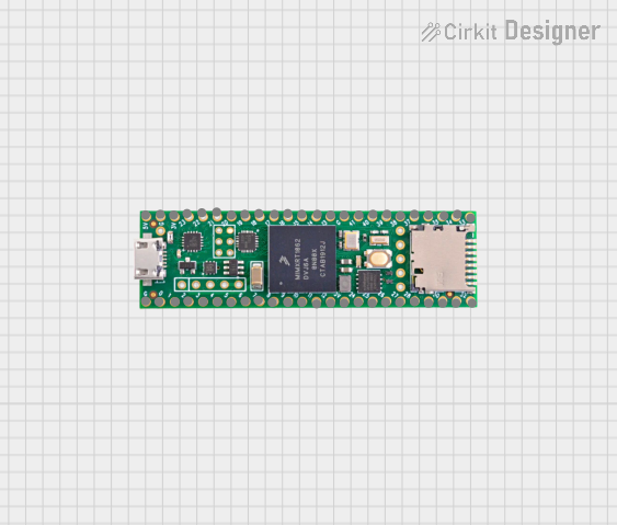 Open Project in Cirkit Designer
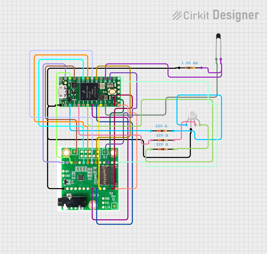 Open Project in Cirkit Designer
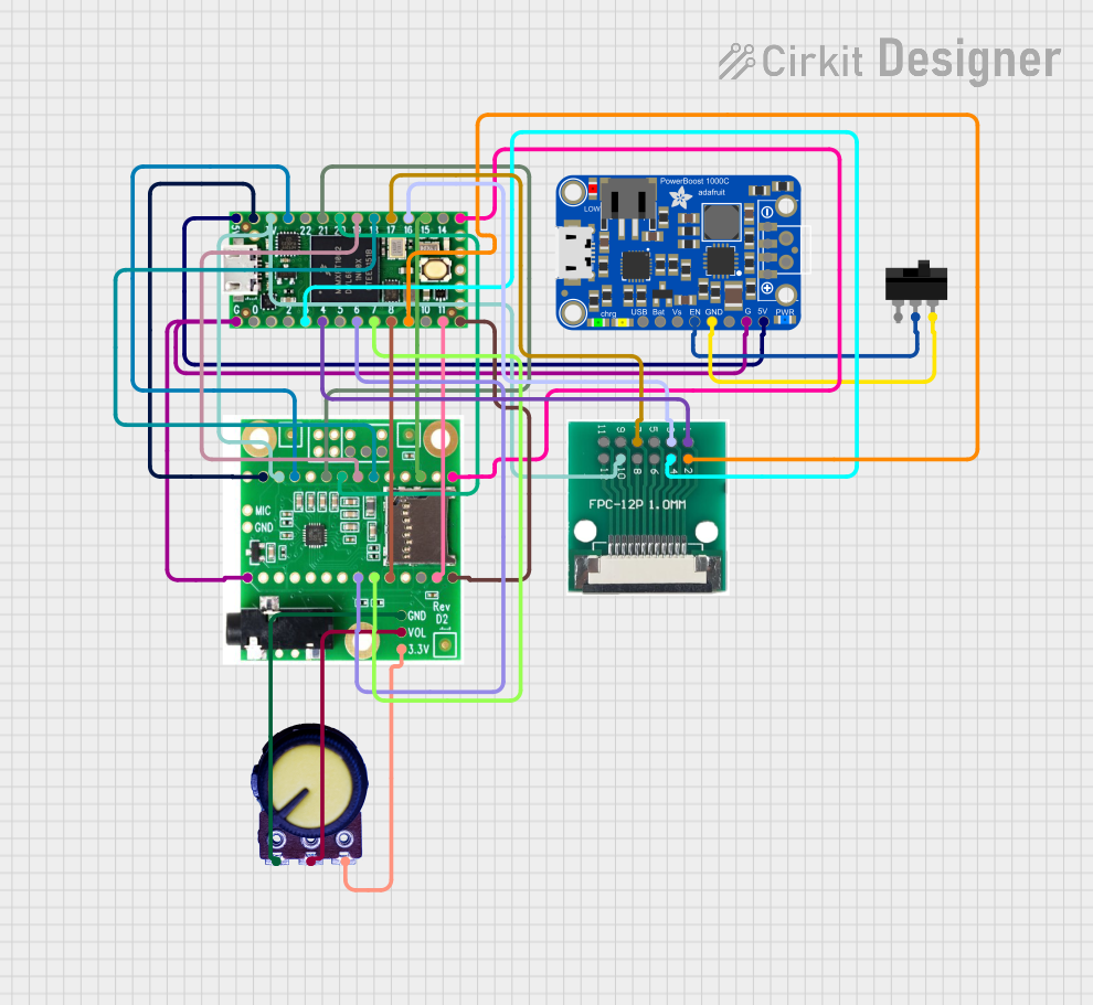 Open Project in Cirkit Designer
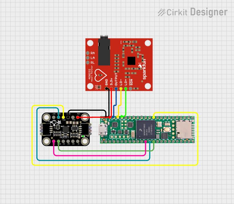 Open Project in Cirkit Designer
Explore Projects Built with Teensy 3.1
Open Project in Cirkit DesignerOpen Project in Cirkit DesignerOpen Project in Cirkit DesignerOpen Project in Cirkit DesignerCommon Applications
- Robotics and automation systems
- Internet of Things (IoT) devices
- Audio signal processing and synthesis
- Data logging and sensor interfacing
- Prototyping and educational projects
Technical Specifications
The following table outlines the key technical details of the Teensy 3.1 microcontroller board:
| Specification | Details |
|---|---|
| Processor | ARM Cortex-M4, 32-bit, 72 MHz |
| RAM | 32 KB |
| Flash Memory | 256 KB |
| EEPROM | 2 KB |
| Operating Voltage | 3.3V |
| Input Voltage (VIN) | 3.6V to 6.0V |
| Digital I/O Pins | 34 |
| PWM Pins | 12 |
| Analog Input Pins | 21 (12-bit ADC) |
| Analog Output Pins | 1 (12-bit DAC) |
| Communication Interfaces | UART, SPI, I2C, I2S, CAN, USB |
| USB Support | USB 2.0 Full Speed (Device Mode) |
| Dimensions | 1.4 x 0.7 inches (35.56 x 17.78 mm) |
Pin Configuration
The Teensy 3.1 has a total of 48 pins, including digital, analog, and power pins. Below is a summary of the pin configuration:
| Pin | Function | Description |
|---|---|---|
| VIN | Power Input | Input voltage (3.6V to 6.0V) |
| 3.3V | Power Output | Regulated 3.3V output |
| GND | Ground | Ground connection |
| A0-A20 | Analog Inputs | 12-bit ADC channels |
| D0-D33 | Digital I/O | General-purpose digital input/output pins |
| PWM | Pulse Width Modulation | 12 pins support PWM for motor control, LEDs, etc. |
| DAC | Digital-to-Analog Converter | 12-bit DAC for analog output |
| I2C | SDA, SCL | I2C communication pins |
| SPI | MOSI, MISO, SCK, CS | SPI communication pins |
| UART | TX, RX | Serial communication pins |
| USB | D+, D-, VBUS, GND | USB data and power pins |
Usage Instructions
How to Use the Teensy 3.1 in a Circuit
Powering the Board:
- Connect the VIN pin to a power source (3.6V to 6.0V) or use the USB port for power and programming.
- Ensure the GND pin is connected to the ground of your circuit.
Programming the Board:
- Install the Arduino IDE and the Teensyduino add-on to enable Teensy support.
- Connect the Teensy 3.1 to your computer via a USB cable.
- Select "Teensy 3.1" as the board in the Arduino IDE.
- Write your code and upload it to the board.
Connecting Peripherals:
- Use the digital I/O pins for sensors, actuators, or other devices.
- Use the analog input pins (A0-A20) for reading sensor data.
- Use the PWM pins for controlling motors or dimming LEDs.
Important Considerations
- The Teensy 3.1 operates at 3.3V logic levels. Ensure that any connected devices are compatible with 3.3V or use level shifters.
- Avoid exceeding the maximum input voltage of 6.0V on the VIN pin to prevent damage.
- Use decoupling capacitors near power pins to reduce noise in sensitive applications.
Example Code for Arduino IDE
The following example demonstrates how to blink an LED connected to pin 13:
// Blink an LED on Teensy 3.1
// This example toggles the LED on pin 13 every 500 milliseconds.

void setup() {
  pinMode(13, OUTPUT); // Set pin 13 as an output
}

void loop() {
  digitalWrite(13, HIGH); // Turn the LED on
  delay(500);             // Wait for 500 milliseconds
  digitalWrite(13, LOW);  // Turn the LED off
  delay(500);             // Wait for 500 milliseconds
}
Troubleshooting and FAQs
Common Issues
The board is not recognized by the computer:
- Ensure the USB cable is properly connected and supports data transfer.
- Check if the Teensyduino add-on is installed in the Arduino IDE.
- Press the reset button on the Teensy 3.1 to enter programming mode.
Code does not upload to the board:
- Verify that "Teensy 3.1" is selected as the board in the Arduino IDE.
- Ensure no other programs are using the USB port.
Connected devices are not working:
- Check the wiring and ensure all connections are secure.
- Confirm that the devices are compatible with 3.3V logic levels.
Tips for Troubleshooting
- Use a multimeter to check voltage levels and continuity in your circuit.
- Test the board with a simple program (e.g., blinking an LED) to verify functionality.
- Consult the Teensy 3.1 datasheet for detailed technical information.
By following this documentation, you can effectively use the Teensy 3.1 for a variety of embedded projects.