Cirkit Designer Logo
Cirkit Designer
Your all-in-one circuit design IDE
Home / 
Component Documentation

How to Use Regulator Stepdown DC XL4015 CC CV: Examples, Pinouts, and Specs

Image of Regulator Stepdown DC XL4015 CC CV
Cirkit Designer LogoDesign with Regulator Stepdown DC XL4015 CC CV in Cirkit Designer

Introduction

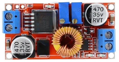
The XL4015 is a highly efficient, DC-DC step-down (buck) converter module capable of regulating and stepping down input voltage levels to a lower, specified output voltage. It is equipped with both constant current (CC) and constant voltage (CV) modes, making it versatile for regulating different types of loads. This module is commonly used in battery charging applications, power supplies, and as a driver for LEDs where precise voltage and current control is required.

Explore Projects Built with Regulator Stepdown DC XL4015 CC CV

Use Cirkit Designer to design, explore, and prototype these projects online. Some projects support real-time simulation. Click "Open Project" to start designing instantly!
Battery-Powered DC Generator with XL4015 Buck Converter
Image of conveyor: A project utilizing Regulator Stepdown DC XL4015 CC CV in a practical application
This circuit consists of a 12V battery connected to a rocker switch, which controls the input to an XL4015 DC Buck Step-down converter. The converter steps down the voltage to power a DC generator, with the generator's output connected back to the converter to form a feedback loop.
Cirkit Designer LogoOpen Project in Cirkit Designer
Battery-Powered Adjustable Voltage Regulator with Li-ion 18650 Batteries and BMS
Image of mini ups: A project utilizing Regulator Stepdown DC XL4015 CC CV in a practical application
This circuit is a power management system that uses four Li-ion 18650 batteries connected to a 2S 30A BMS for battery management and protection. The system includes step-up and step-down voltage regulators to provide adjustable output voltages, controlled by a rocker switch, and multiple DC jacks for power input and output.
Cirkit Designer LogoOpen Project in Cirkit Designer
Smart DC Motor Control System with Relay and Capacitive Sensors
Image of conveyor: A project utilizing Regulator Stepdown DC XL4015 CC CV in a practical application
This circuit controls two DC motors using a combination of relays, a toggle switch, and capacitive sensors. The XL4015 DC Buck Step-down module provides regulated power, while the capacitive sensors and toggle switch are used to control the relays, which in turn manage the operation of the motors.
Cirkit Designer LogoOpen Project in Cirkit Designer
Dual Motor Control Circuit with Directional Switching and Voltage Regulation
Image of Pencuci Kipas: A project utilizing Regulator Stepdown DC XL4015 CC CV in a practical application
This circuit features a 12V battery connected through a rocker switch to two buck converters, one of which steps down the voltage to power two DC mini metal gear motors, and the other is connected to a directional switch that controls a third DC mini metal gear motor. The XL4015 5A DC Buck Step-down converter's output is connected to two motors, allowing them to run at a reduced voltage, while the other buck converter's output is routed through a directional switch to control the direction of the third motor.
Cirkit Designer LogoOpen Project in Cirkit Designer

Explore Projects Built with Regulator Stepdown DC XL4015 CC CV

Use Cirkit Designer to design, explore, and prototype these projects online. Some projects support real-time simulation. Click "Open Project" to start designing instantly!
Image of conveyor: A project utilizing Regulator Stepdown DC XL4015 CC CV in a practical application
Battery-Powered DC Generator with XL4015 Buck Converter
This circuit consists of a 12V battery connected to a rocker switch, which controls the input to an XL4015 DC Buck Step-down converter. The converter steps down the voltage to power a DC generator, with the generator's output connected back to the converter to form a feedback loop.
Cirkit Designer LogoOpen Project in Cirkit Designer
Image of mini ups: A project utilizing Regulator Stepdown DC XL4015 CC CV in a practical application
Battery-Powered Adjustable Voltage Regulator with Li-ion 18650 Batteries and BMS
This circuit is a power management system that uses four Li-ion 18650 batteries connected to a 2S 30A BMS for battery management and protection. The system includes step-up and step-down voltage regulators to provide adjustable output voltages, controlled by a rocker switch, and multiple DC jacks for power input and output.
Cirkit Designer LogoOpen Project in Cirkit Designer
Image of conveyor: A project utilizing Regulator Stepdown DC XL4015 CC CV in a practical application
Smart DC Motor Control System with Relay and Capacitive Sensors
This circuit controls two DC motors using a combination of relays, a toggle switch, and capacitive sensors. The XL4015 DC Buck Step-down module provides regulated power, while the capacitive sensors and toggle switch are used to control the relays, which in turn manage the operation of the motors.
Cirkit Designer LogoOpen Project in Cirkit Designer
Image of Pencuci Kipas: A project utilizing Regulator Stepdown DC XL4015 CC CV in a practical application
Dual Motor Control Circuit with Directional Switching and Voltage Regulation
This circuit features a 12V battery connected through a rocker switch to two buck converters, one of which steps down the voltage to power two DC mini metal gear motors, and the other is connected to a directional switch that controls a third DC mini metal gear motor. The XL4015 5A DC Buck Step-down converter's output is connected to two motors, allowing them to run at a reduced voltage, while the other buck converter's output is routed through a directional switch to control the direction of the third motor.
Cirkit Designer LogoOpen Project in Cirkit Designer

Technical Specifications

Key Technical Details

  • Input Voltage Range: 4V to 38V DC
  • Output Voltage Range: 1.25V to 36V DC (adjustable)
  • Output Current: Up to 5A (with proper heat sinking)
  • Maximum Output Power: 75W (with proper heat sinking)
  • Conversion Efficiency: Up to 96%
  • Switching Frequency: 180kHz
  • Operating Temperature: -40°C to +85°C

Pin Configuration and Descriptions

Pin Number Name Description
1 IN+ Input voltage positive terminal
2 IN- Input voltage negative terminal
3 OUT+ Output voltage positive terminal
4 OUT- Output voltage negative terminal
5 CV Constant voltage adjustment potentiometer
6 CC Constant current adjustment potentiometer

Usage Instructions

How to Use the Component in a Circuit

  1. Connection: Connect the input voltage to the IN+ and IN- terminals, ensuring that the input does not exceed the module's maximum voltage rating.
  2. Output Voltage Adjustment: Turn the CV potentiometer to adjust the output voltage to the desired level. Use a multimeter to monitor the voltage at the OUT+ and OUT- terminals.
  3. Output Current Adjustment: If operating in CC mode, adjust the CC potentiometer to set the maximum current limit. This is particularly useful when charging batteries or driving LEDs.
  4. Load Connection: Connect the load to the OUT+ and OUT- terminals. Ensure that the load does not draw more current than the module's maximum rating.
  5. Heat Management: For applications drawing high current or operating at high power, attach a heat sink to the module to prevent overheating.

Important Considerations and Best Practices

  • Always verify input and output voltages with a multimeter before connecting sensitive loads.
  • Gradually adjust the potentiometers while monitoring the changes to prevent damage to the load.
  • Ensure that the input voltage is at least 1.5V higher than the desired output voltage for proper regulation.
  • Avoid adjusting the potentiometers while the module is under high load to prevent voltage/current spikes.
  • Use adequate wiring thickness to handle the current without excessive voltage drop or overheating.

Troubleshooting and FAQs

Common Issues and Solutions

  • Output voltage does not match the setting: Re-calibrate the CV potentiometer and check for any loose connections.
  • Module overheats: Ensure proper heat sinking is in place, reduce the load, or improve airflow around the module.
  • Inconsistent output current: Verify that the CC potentiometer is correctly adjusted and that the load does not exceed the module's specifications.

FAQs

Q: Can I use the XL4015 to charge lithium batteries? A: Yes, the XL4015 can be used to charge lithium batteries by setting the CV to the battery's charge voltage and the CC to the desired charge current.

Q: What is the difference between CC and CV modes? A: In CV mode, the module regulates the output voltage to a fixed level regardless of the load, while in CC mode, it regulates the output current, which is useful for applications like battery charging or LED driving where current limiting is required.

Q: How do I know if I need a heat sink? A: If the module is operating at high power levels or the ambient temperature is high, a heat sink is recommended to prevent overheating and ensure reliable operation.

Example Code for Arduino UNO

The XL4015 does not require any code for basic operation. However, if you wish to monitor the output voltage or current using an Arduino UNO, you can use the following example code to read analog values from the module's output.

// Define the analog input pin connected to the output voltage
const int analogPin = A0;

void setup() {
  // Initialize serial communication at 9600 baud rate
  Serial.begin(9600);
}

void loop() {
  // Read the analog value from the output voltage
  int sensorValue = analogRead(analogPin);
  
  // Convert the analog reading (which goes from 0 - 1023) to a voltage (0 - 5V)
  float voltage = sensorValue * (5.0 / 1023.0);
  
  // Print out the voltage to the Serial Monitor
  Serial.println(voltage);
  
  // Wait for a second before reading again
  delay(1000);
}

Note: This code assumes that the output voltage of the XL4015 is within the 0-5V range that the Arduino can read. If the voltage is higher, you will need a voltage divider to scale down the voltage to a safe level for the Arduino's analog input.