How to Use G-Bro: Examples, Pinouts, and Specs
Introduction
The G-Bro (Manufacturer Part ID: 1001) is a versatile signal processing and amplification component developed by LinkX Lab. It is designed to enhance signal quality in audio and communication systems, making it an essential component for applications requiring high-fidelity signal amplification and noise reduction. The G-Bro is particularly valued for its compact design, low power consumption, and robust performance in both analog and digital circuits.
Explore Projects Built with G-Bro


Explore Projects Built with G-Bro
Common Applications
- Audio signal amplification in speaker systems
- Noise reduction in communication devices
- Signal conditioning in sensor systems
- Pre-amplification for microphones and audio recording equipment
- Use in RF (radio frequency) circuits for signal boosting
Technical Specifications
The G-Bro is engineered to deliver reliable performance across a range of operating conditions. Below are its key technical specifications:
| Parameter | Value |
|---|---|
| Supply Voltage (Vcc) | 3.3V to 12V |
| Operating Current | 10mA (typical), 20mA (maximum) |
| Gain | Adjustable, up to 40 dB |
| Frequency Range | 20 Hz to 20 kHz (audio range) |
| Input Impedance | 10 kΩ |
| Output Impedance | 600 Ω |
| Operating Temperature | -20°C to +85°C |
| Package Type | 8-pin DIP or SMD |
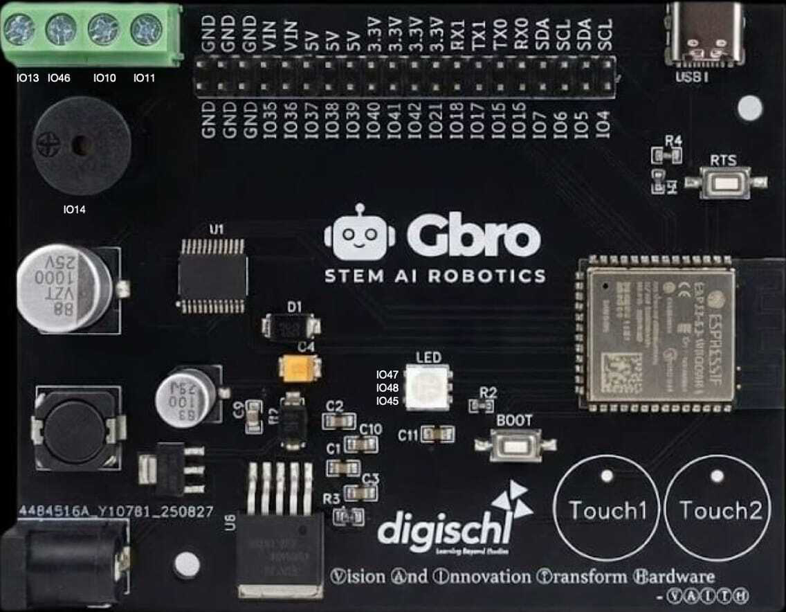
Pin Configuration and Descriptions
The G-Bro features an 8-pin configuration, as detailed below:
| Pin Number | Pin Name | Description |
|---|---|---|
| 1 | Vcc | Positive power supply input (3.3V to 12V) |
| 2 | IN+ | Non-inverting signal input |
| 3 | IN- | Inverting signal input |
| 4 | GND | Ground connection |
| 5 | OUT | Amplified signal output |
| 6 | GAIN | Gain adjustment pin (connect resistor or potentiometer) |
| 7 | NC | No connection (leave unconnected) |
| 8 | SHDN | Shutdown control (active low) |
Usage Instructions
The G-Bro is straightforward to integrate into circuits for signal amplification and processing. Follow the steps below to use it effectively:
Basic Circuit Setup
- Power Supply: Connect the Vcc pin (Pin 1) to a regulated power source (3.3V to 12V) and the GND pin (Pin 4) to the circuit ground.
- Signal Input: Feed the input signal to the IN+ (Pin 2) and IN- (Pin 3) pins. For single-ended input, connect IN- to ground.
- Signal Output: Connect the OUT pin (Pin 5) to the load or next stage of the circuit.
- Gain Adjustment: Use a resistor or potentiometer between the GAIN pin (Pin 6) and ground to set the desired gain level.
- Shutdown Control: To enable the G-Bro, ensure the SHDN pin (Pin 8) is pulled high. Pull it low to disable the component.
Important Considerations
- Decoupling Capacitors: Place a 0.1 µF ceramic capacitor close to the Vcc pin to filter noise from the power supply.
- Thermal Management: Ensure adequate ventilation or heat sinking if operating at high gain levels for extended periods.
- Input Signal Levels: Avoid exceeding the maximum input voltage to prevent distortion or damage to the component.
Example: Using G-Bro with Arduino UNO
The G-Bro can be used with an Arduino UNO for audio signal amplification. Below is an example of how to connect and control the G-Bro:
Circuit Connections
- Connect the G-Bro's Vcc pin to the Arduino's 5V pin.
- Connect the GND pin to the Arduino's GND.
- Feed an audio signal to the IN+ pin, and connect IN- to GND.
- Connect the OUT pin to a speaker or audio output device.
- Use a digital pin on the Arduino to control the SHDN pin.
Arduino Code Example
// Example code to control the G-Bro component with Arduino UNO

const int shutdownPin = 7; // Pin connected to G-Bro's SHDN pin

void setup() {
  pinMode(shutdownPin, OUTPUT); // Set shutdown pin as output
  digitalWrite(shutdownPin, HIGH); // Enable the G-Bro (active high)
}

void loop() {
  // Amplifier is enabled and running
  // Add your signal processing code here if needed

  delay(1000); // Keep the amplifier running
}
Troubleshooting and FAQs
Common Issues and Solutions
No Output Signal
- Cause: SHDN pin is not properly configured.
- Solution: Ensure the SHDN pin is pulled high to enable the G-Bro.
Distorted Output
- Cause: Input signal level is too high or gain is set too high.
- Solution: Reduce the input signal amplitude or adjust the gain resistor.
Excessive Noise
- Cause: Insufficient power supply filtering or poor grounding.
- Solution: Add decoupling capacitors near the Vcc pin and ensure a solid ground connection.
Overheating
- Cause: Prolonged operation at high gain levels.
- Solution: Improve ventilation or add a heat sink to the component.
FAQs
Q: Can the G-Bro be used for RF signal amplification?
A: Yes, the G-Bro can amplify RF signals within its frequency range, but ensure proper impedance matching for optimal performance.
Q: What is the maximum gain I can achieve with the G-Bro?
A: The G-Bro supports a maximum gain of 40 dB, adjustable via the GAIN pin.
Q: Is the G-Bro compatible with 3.3V systems?
A: Yes, the G-Bro operates with supply voltages as low as 3.3V, making it suitable for low-power systems.
Q: Can I leave the NC pin unconnected?
A: Yes, the NC (No Connection) pin does not need to be connected to any circuit.